
Curlable wind barrier structure

A wind barrier and curling technology, applied in the field of wind barrier structures and rollable wind barrier structures, can solve the problems of no wind barrier structure, no wind shield structure, fixed barrier strips can not meet the expansion and displacement, etc., to achieve continuous Sexuality, beneficial to the effect of driving safety

Active Publication Date: 2017-01-25
TONGJI UNIV +1
View PDF5 Cites 0 Cited by
  • Summary
  • Abstract
  • Description
  • Claims
  • Application Information

AI Technical Summary

Problems solved by technology

[0002] At present, in the bridges with wind barrier structure at home and abroad, the wind barrier structure is mostly set on the continuous beam section of the main bridge or approach bridge, but for the beam section with longitudinal displacement, such as the beam section where the expansion joint is located, the traditional form of fixing Barrier strips cannot meet the needs of expansion and displacement, so no wind barrier structure is set up
The same situation also has the beam section near the bridge tower. Since the beam section generally reduces the section width near the bridge tower, the wind barrier structure arranged on the outside of the beam section has to be disconnected near the bridge tower, and the bridge tower and the nearby beam section The distance between them also changes with the longitudinal displacement of the bridge, so there is no windshield structure on both sides of the bridge tower

Method used


Image

  • Curlable wind barrier structure
  • Curlable wind barrier structure
  • Curlable wind barrier structure

Examples


Embodiment Construction

[0015] The invention will be further described below in conjunction with the embodiments shown in the accompanying drawings.

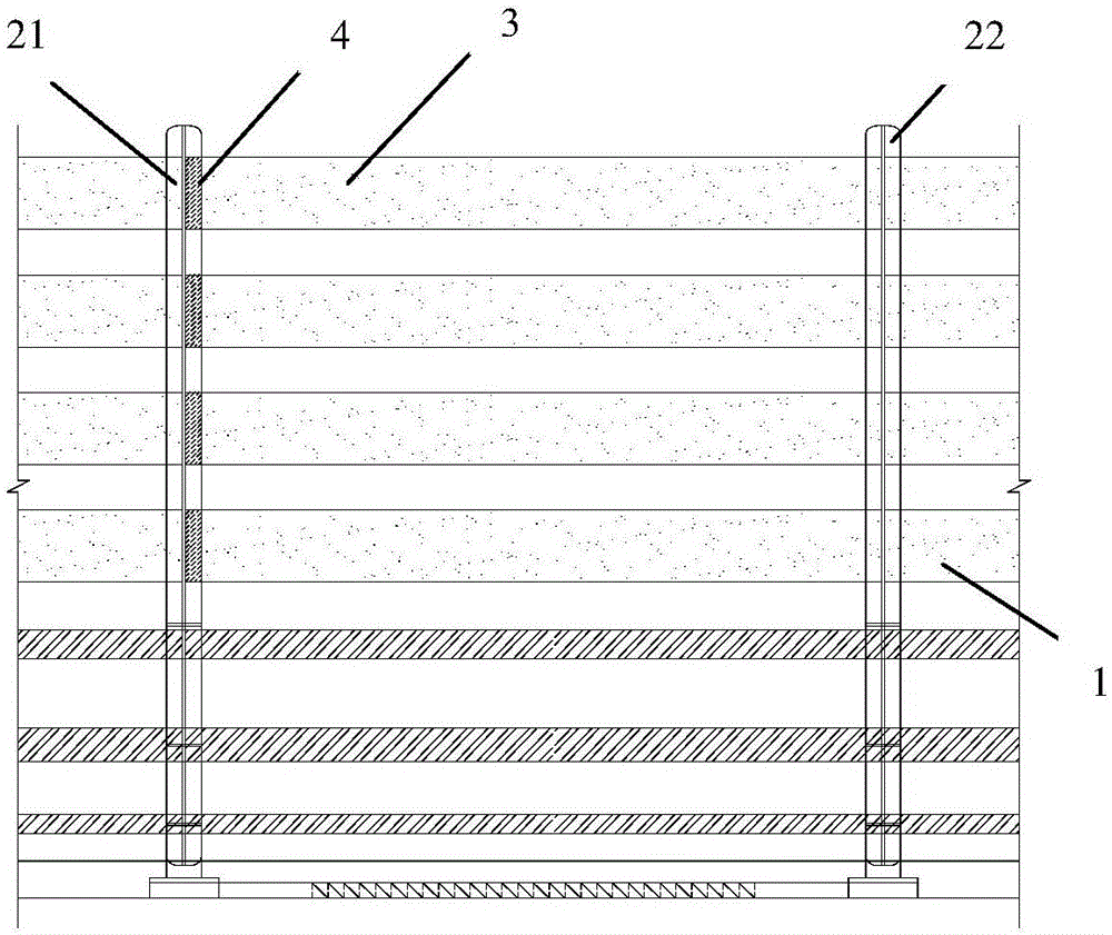
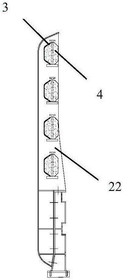
[0016] Such as Figure 1A with Figure 1B As shown, a rollable bridge wind barrier structure of the present invention includes a left wind barrier support 21 and a right wind barrier support 22, and several wind barrier supports 21 and right wind barrier supports 22 parallel to each other. Rollable barrier strips 3, wherein one side end of each barrier strip 3 is provided with a curling portion 4;

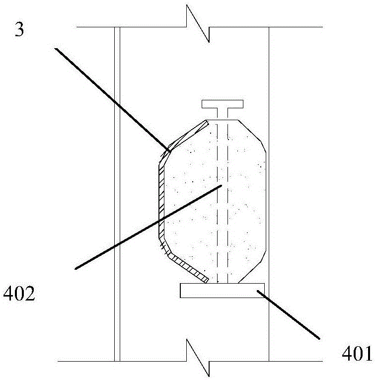
[0017] The crimped part 4 is formed by crimping the end of the barrier bar 3 around the axis 402. The crimped part 4 is placed on the bottom plate 401, and the bottom plate 401 is fixedly connected with the web supported by the wind barrier. The end of the crimped barrier bar 3 is connected to a force-back device 5, which can ensure the free contraction of the barrier bar in the crimped section. It can be seen that the present invention has the function o...


PUM


Abstract

A curlable wind barrier structure comprises wind barrier supports and a plurality of barrier strips erected on the wind barrier supports, wherein a curly part is arranged at one side end of each barrier strip and is formed by curling the end of each barrier strip around the axis, the curly parts are placed on bottom plates, and the bottom plates are fixedly connected with webs of the wind barrier supports; the ends of the curly barrier strips are connected with auxiliary devices to guarantee contraction of the barrier strips of the curly parts, and wind screening area change caused by beam section deflection can be adapted. The structure has the advantages that the structure is simple and practical, the wind screening requirement of deflected beam sections can be met, and the traveling safety of a bridge deck is improved. During usage, the length of the barrier strips can be adjusted along with deflection of the beam sections by the aid of curly force return devices (or memory alloys), so that the barrier strips always exist in a wind screening area, and thus the wind barrier has good adaptability to deflection of the beam sections.

Description

technical field [0001] The invention belongs to the field of bridge engineering and relates to a wind barrier structure, in particular to a rollable wind barrier structure. Background technique [0002] At present, in the bridges with wind barrier structure at home and abroad, the wind barrier structure is mostly set on the continuous beam section of the main bridge or approach bridge, but for the beam section with longitudinal displacement, such as the beam section where the expansion joint is located, the traditional form of fixing Barrier strips cannot meet the needs of expansion and displacement, so no wind barrier structure is set up. The same situation also has the beam section near the bridge tower. Since the beam section generally reduces the section width near the bridge tower, the wind barrier structure arranged on the outside of the beam section has to be disconnected near the bridge tower, and the bridge tower and the nearby beam section The distance between the...

Claims


Application Information

Patent Timeline
IPC IPC(8): E01F8/00
CPCE01F8/0011E01F8/0023
Inventor 王达磊陈程马如进陈艾荣李承宬
Owner TONGJI UNIV
Learn More