

Rotary vacuum hydrogen breaking device
A rotary and vacuum technology, applied in the field of production equipment of rare earth magnetic materials, can solve the problems of no automation, high cost, and difficulty in forming automation, and achieve the effect of continuity
- Summary
- Abstract
- Description
- Claims
- Application Information
AI Technical Summary
Problems solved by technology
Method used
Image

Examples
Embodiment 1
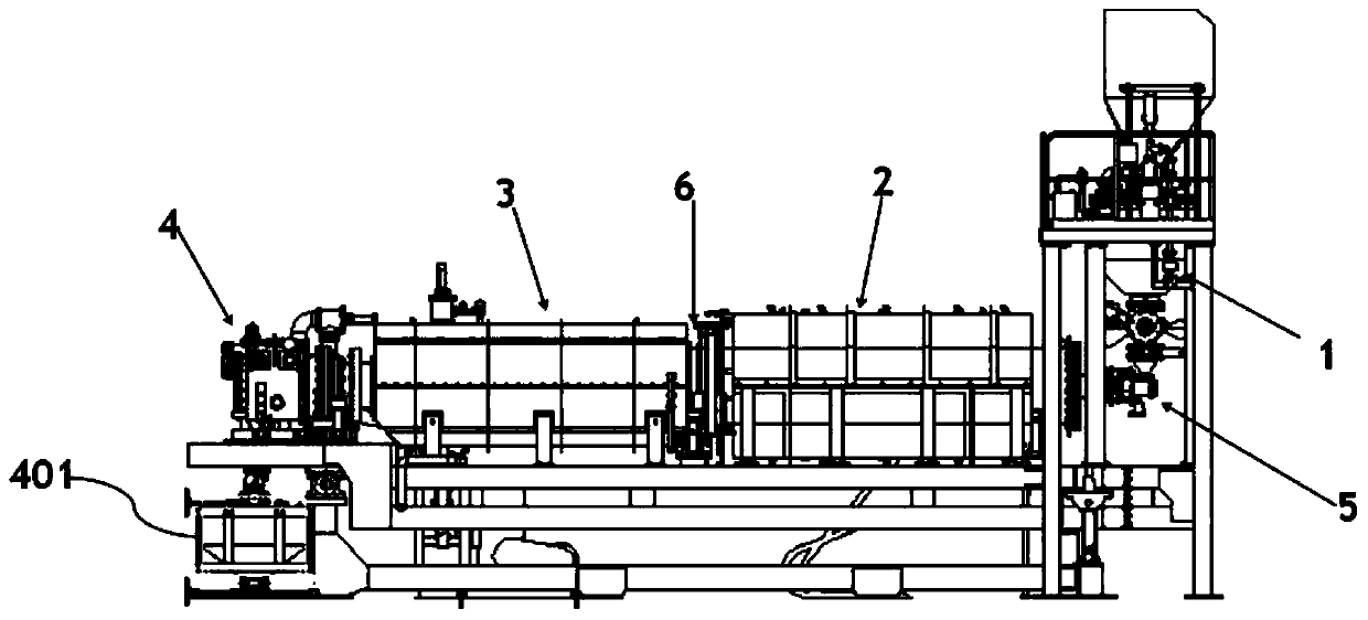
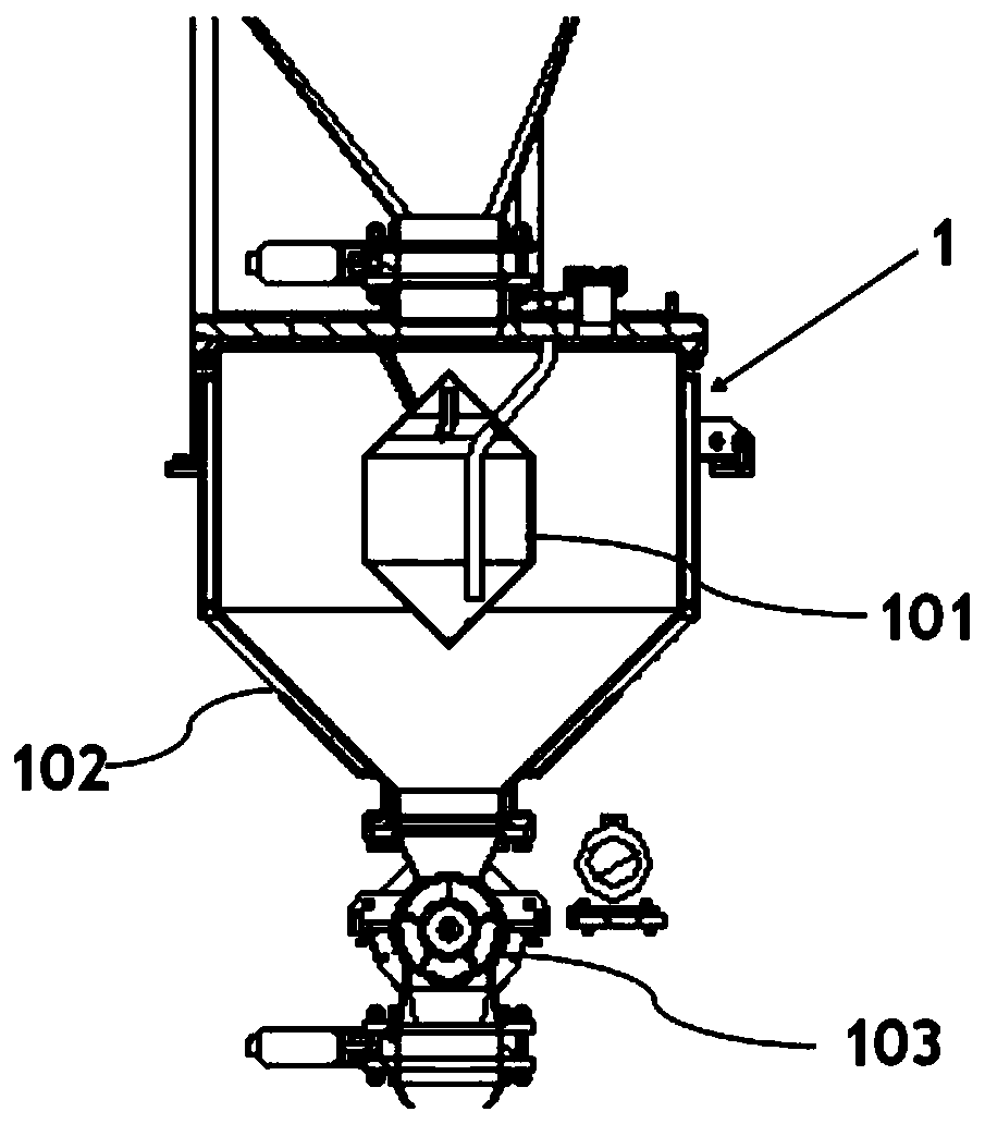
[0037] Such as figure 1 As shown, a rotary vacuum hydrogen breaking device includes a hydrogen absorption chamber 1, a rotating heating cylinder 2, a rotating cooling cylinder 3 and a discharge chamber 4; the feed port of the hydrogen absorption chamber 1 is connected with the feeding cylinder, and the hydrogen absorption chamber The first vacuum butterfly valve and the second vacuum butterfly valve are respectively arranged at the feed port and the discharge port of 1; the rotating heating cylinder 2 is connected with the discharge port of the hydrogen absorption chamber 1 through the screw feeding shaft 5, and the inside of the rotating heating cylinder 2 A material conveying mechanism 7 is provided; the rotating cooling cylinder 3 communicates with the rotating heating cylinder 2 through a flange 6, and another material conveying mechanism 7 is arranged in the rotating cooling cylinder 3; the discharge chamber 4 is connected with the rotating cooling cylinder 3, and The mat...
Embodiment 2
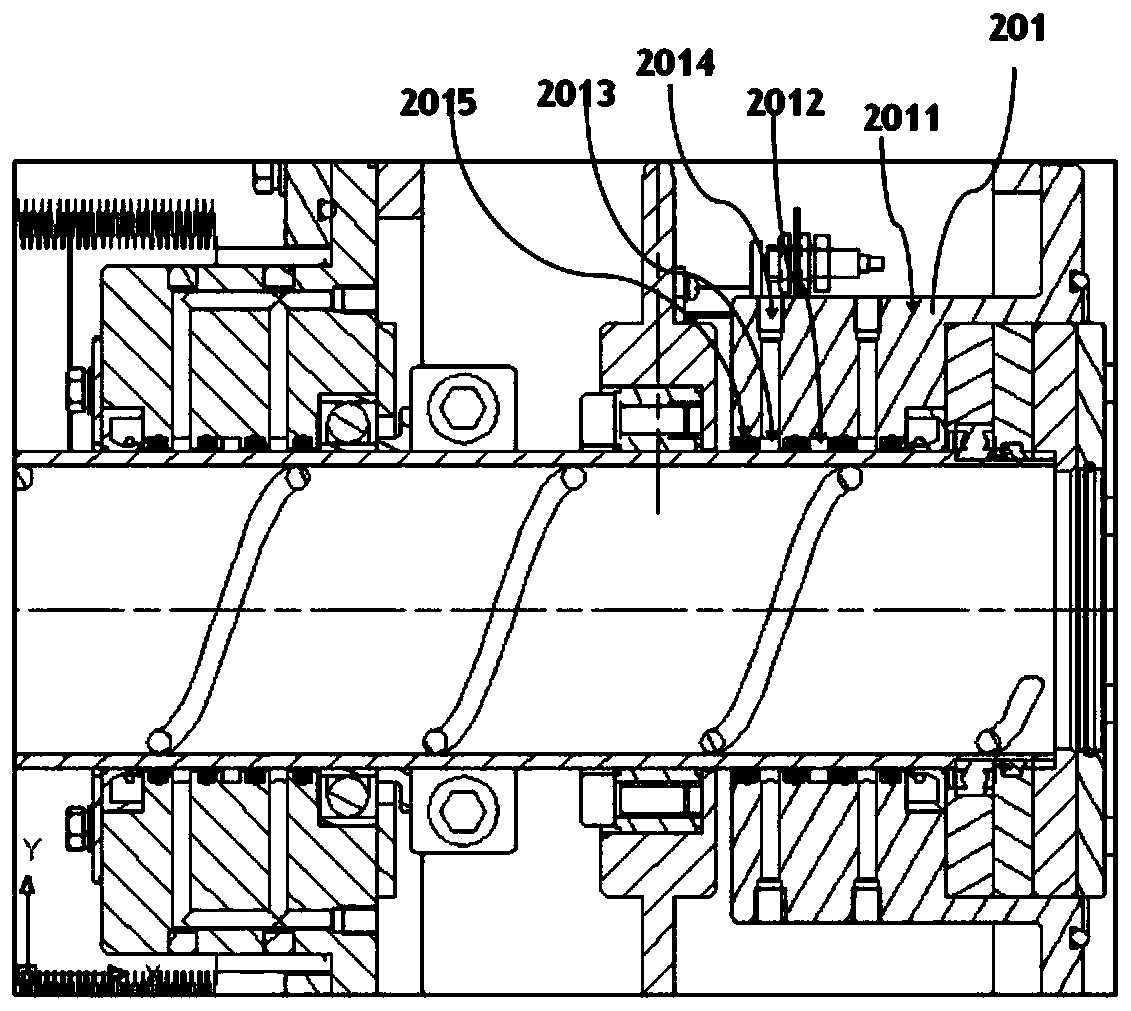
[0052] A rotary vacuum hydrogen breaking device provided with reference to Example 1 provided with reference to Example 1 is different in that, as Figure 5 As shown, the material conveying mechanism 7 includes a rotating thread groove 703 arranged on the inner wall of the rotating heating cylinder 2 or the rotating cooling cylinder 3, and the rotating thread groove 703 is used for forward or reverse rotation of the rotating heating cylinder 2 or the rotating cooling cylinder 3 Next, the material in the rotating heating cylinder 2 or the rotating cooling cylinder 3 is transferred between the end near the feeding chamber 1 and the end near the discharging chamber 2.
[0053] When the material to be processed is lumpy, if the material is conveyed by rotating blades, the material is easily stuck between the bushing of the screw feed shaft and the screw blade during the transfer process, and the screw feed shaft will stop rotating at this time. In order to eliminate this phenomeno...
PUM
 Abstract
Description
Claims
Application Information