Automatic thermocouple verifying system

A thermocouple, automatic technology, applied in the direction of measuring heat, measuring devices, instruments, etc., can solve the problems of low efficiency and inability to detect the thermocouple automatic verification system, and achieve the effect of realizing uninterrupted and improving efficiency.

Inactive Publication Date: 2013-08-28
包金英
View PDF6 Cites 2 Cited by
  • Summary
  • Abstract
  • Description
  • Claims
  • Application Information

AI Technical Summary

Problems solved by technology

However, during the cooling process of the verification furnace, the entire automatic thermocouple verification system is in a

Method used


Image

  • Automatic thermocouple verifying system

Examples


Embodiment Construction

[0008] The present invention will be described in further detail below through specific implementation examples and in conjunction with the accompanying drawings.

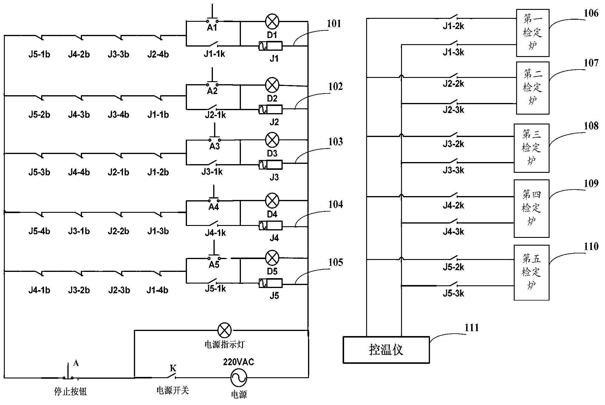
[0009] Such as figure 1 As shown, a thermocouple automatic verification system includes a temperature controller 111, a switching device and multiple verification furnaces electrically connected to the temperature controller 111 respectively; the switching device is used to switch the temperature controller 111 and any The on-off between the test furnaces.

[0010] The thermocouple automatic verification system includes multiple verification furnaces. During the cooling process of one verification furnace, the switching device can cut off the connection between the cooling verification furnace and the temperature controller 111, and then put the other one on standby. The verification furnace in the tester is connected to the temperature controller 111, so that the verification furnace is waiting for the working st...


PUM


Abstract

The invention relates the field of thermocouple verifying systems, in particular to an automatic thermocouple verifying system which comprises a temperature controlling instrument, a switching device and multiple verifying furnaces which are respectively electrically connected with the temperature controlling instrument. The switching device is used for switching make-and-break between the temperature control instrument and any of the verifying furnaces. The automatic thermocouple verifying system does not need to wait for detection until the verifying furnaces are cooled so as to achieve continuous detection and improves the efficiency of the automatic thermocouple verifying system.

Description

technical field [0001] The invention relates to the field of thermocouple verification systems, in particular to an automatic thermocouple verification system. Background technique [0002] At present, the thermocouple automatic verification system includes a microcomputer, a detector, a temperature controller and a verification furnace. The detector and the temperature controller are respectively electrically connected to the microcomputer; the temperature controller and the detector are respectively electrically connected to the verification furnace. The temperature controller realizes the control of the furnace temperature of the verification furnace by changing the heating voltage of the verification furnace. When the furnace temperature of the verification furnace reaches a predetermined temperature in the detection requirements, the detector detects the thermoelectric potential of the thermocouple placed in the verification furnace, and sends the detected thermoelectr...

Claims


Application Information

Patent Timeline
IPC IPC(8): G01K15/00
Inventor 沈艳秋
Owner 包金英
Why Eureka
Try Eureka