Sliding block pin device for die-casting

A pin and slider technology, which is applied in the field of die-casting slider pin devices, can solve problems such as unfavorable molding, difficult control, and increased costs, and achieve the effect of achieving continuity and reducing the probability of fracture

Inactive Publication Date: 2011-06-22
SUZHOU CHUNXING PRECISION MECHANICAL
View PDF0 Cites 2 Cited by
  • Summary
  • Abstract
  • Description
  • Claims
  • Application Information

AI Technical Summary

Problems solved by technology

[0004] However, the first method is difficult to control, too little spraying will easily increase the holding force, and too much spraying is not

Method used


Image

  • Sliding block pin device for die-casting
  • Sliding block pin device for die-casting

Examples


Embodiment Construction

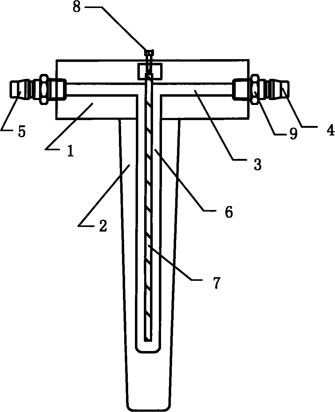
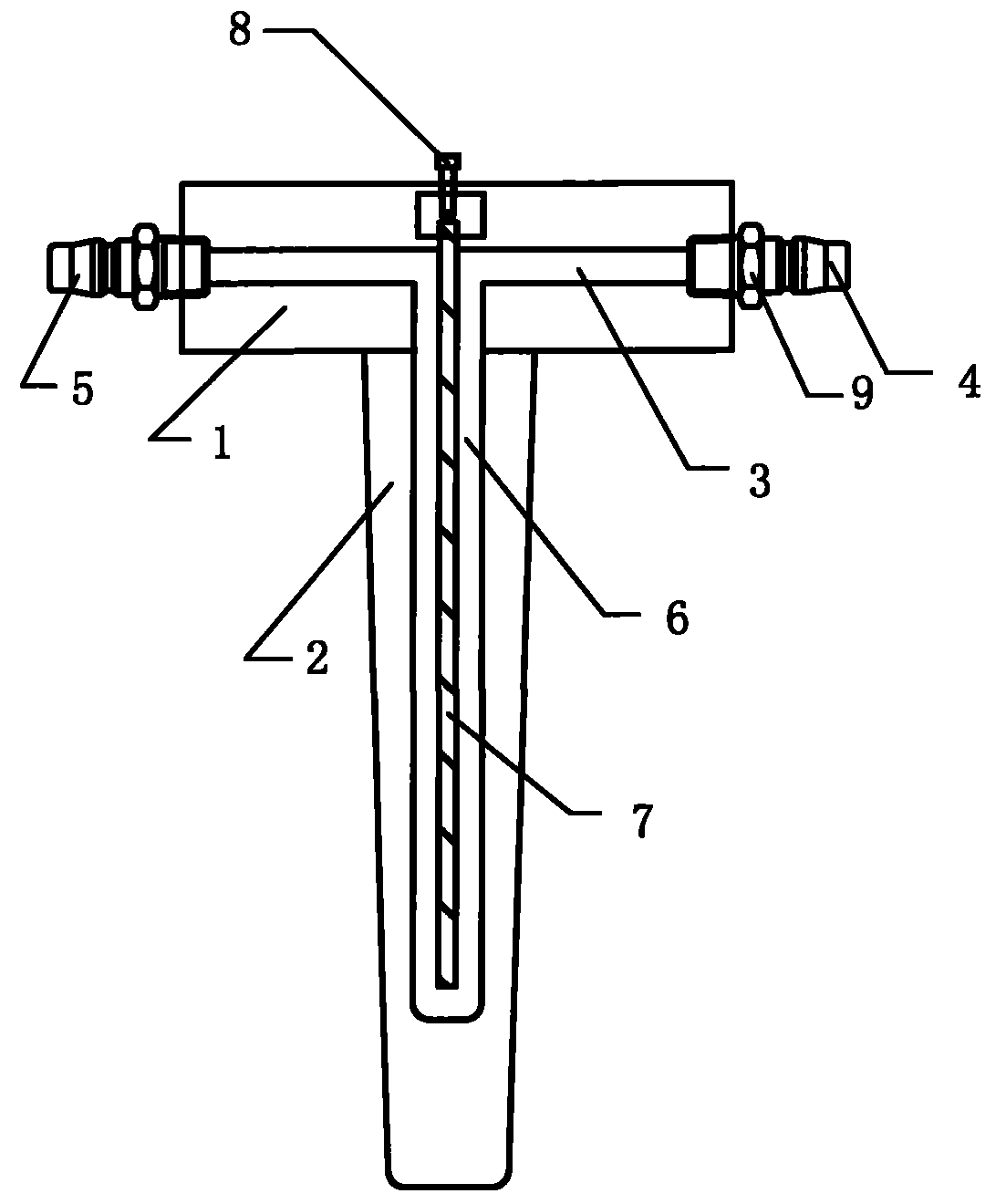
[0020] Such as figure 1 The shown die-casting slider pin 2 device includes an insert 1, and the pin 2 is arranged on the insert 1. Its special feature is that the main water channel 3 is arranged inside the insert 1, and the water channel Water outlet 4 and water inlet 5 are respectively provided at both ends of the pin 2; auxiliary water channel 6 is provided in the pin 2, and the main water channel 3 is connected.

[0021] Looking further, in order to better control the water flow in the main waterway channel 3 and the auxiliary waterway channel 6, that is to control the water inlet and outlet methods, so that the water flow can be fully and smoothly in the main waterway channel 3 and the auxiliary waterway channel 6 orderly flow, the auxiliary water channel 6 is provided with a water barrier 7, one end of the water barrier 7 is fixed on the insert 1, and the other end is not in contact with the inner wall of the auxiliary water channel 6.

[0022] At the same time, in view...


PUM


Abstract

The invention relates to a sliding block pin device for die-casting, which comprises an insert that is provided with a pin, and is characterized in that the insert is internally provided with a main waterway channel; the two ends of the waterway channel are respectively provided with a water outlet and a water inlet; meanwhile, the pin is internally provided with an auxiliary waterway channel communicated with the main waterway channel. Therefore, the pin has the function of water cooling. The sliding block pin device not only reduces the probability of breakage caused by thermal fatigue, but also is beneficial to attachment of release agent, thus realizing the continuity of production and being worth popularization.

Description

technical field [0001] The invention relates to a pin, in particular to a slider pin device for die casting. Background technique [0002] As we all know, in the foundry industry, the mold is a vital link. An important factor affecting the mold is the slider, because the slider is a dynamic factor affecting the product. However, in actual production, the long pins on the slider are easily broken. The long pin on the slider is at high temperature for a long time, and it is difficult for the release agent to adhere to the pin. When the mold is demoulded, the aluminum liquid will have a strong holding force on the pin, which will easily cause the pin to break; On the other hand, if the pin is at high temperature for a long time, the thermal fatigue will be aggravated, which will also cause the pin to break easily. [0003] Now there are probably two ways to solve this situation: one is to increase the amount of spray on the pin by controlling the spray. The other is to repl...

Claims


Application Information

Patent Timeline
IPC IPC(8): B22D17/24
Inventor 孙洁晓万智谢平
Owner SUZHOU CHUNXING PRECISION MECHANICAL
Why Eureka
Try Eureka