Rotary vacuum heat treatment device

A vacuum heat treatment and rotary technology, which is applied in pressure vessels/vacuum vessels, chemical/physical/physicochemical mobile reactors, pressure vessels used in chemical processes, etc., can solve problems such as air leakage and difficult design of vacuum sealing structures , to achieve the effect of continuous

Pending Publication Date: 2019-06-25
沈阳广泰真空科技股份有限公司
View PDF0 Cites 1 Cited by
  • Summary
  • Abstract
  • Description
  • Claims
  • Application Information

AI Technical Summary

Problems solved by technology

[0003] However, the existing rotary heat treatment equipment refers to the heat treatment carried out under atmospheric pressure or atmospheric gas pressure. Because the hea

Method used


Image

  • Rotary vacuum heat treatment device
  • Rotary vacuum heat treatment device
  • Rotary vacuum heat treatment device

Examples


Example Embodiment

[0037] Example 1

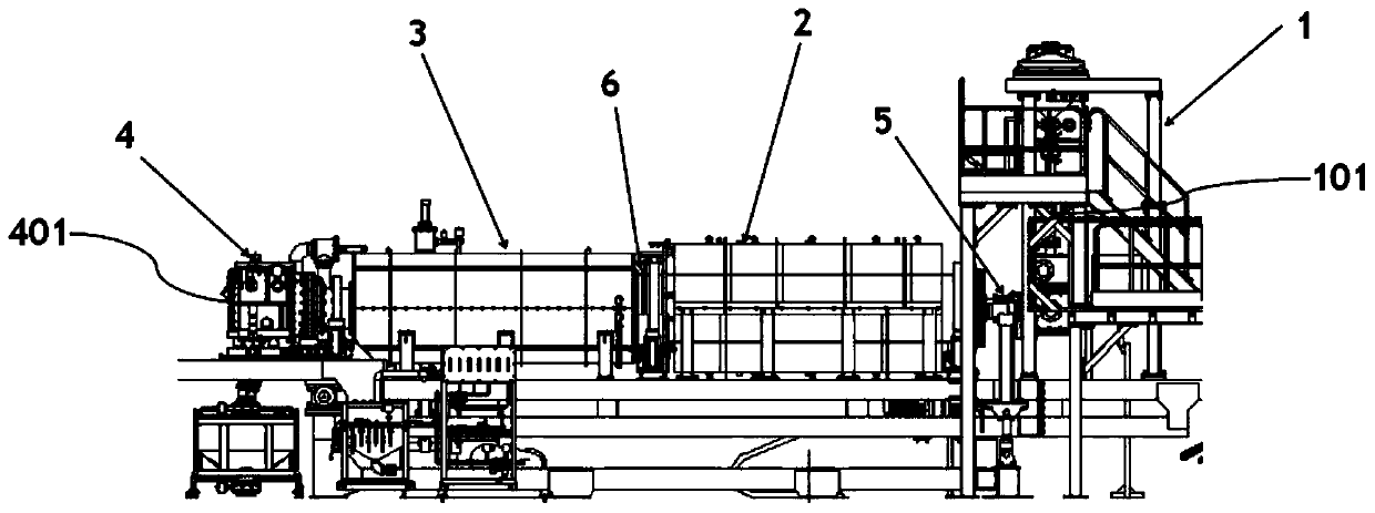
[0038] like figure 1 As shown, a rotary vacuum heat treatment device includes a feeding chamber 1, a rotating heating cylinder 2, a rotating cooling cylinder 3 and a discharge chamber 4; A vacuum butterfly valve; the rotating heating cylinder 2 is connected with the feeding cylinder 101 through the screw feeding shaft 5, and the material conveying mechanism 7 is arranged inside the rotating heating cylinder 2; the rotating cooling cylinder 3 is connected with the rotating heating cylinder 2 through the flange 6, and the rotating Another material conveying mechanism 7 is arranged in the cooling cylinder 3; the discharge chamber 4 is connected with the rotating cooling cylinder 3, and the discharge chamber 4 includes a discharge cylinder 401 and a second vacuum set at the outlet of the discharge cylinder 401. Butterfly valve.

[0039] A rotary vacuum heat treatment device according to the embodiment of the present invention, by connecting the feeding chamber...

Example Embodiment

[0050] Example 2

[0051] A rotary vacuum heat treatment device provided with reference to Example 1 provided with reference to Example 1 is different in that, as Figure 4 As shown, the material conveying mechanism 7 includes a rotating thread groove 703 arranged on the inner wall of the rotating heating cylinder 2 or the rotating cooling cylinder 3, and the rotating thread groove 703 is used for forward or reverse rotation of the rotating heating cylinder 2 or the rotating cooling cylinder 3 Next, the material in the rotating heating cylinder 2 or the rotating cooling cylinder 3 is transferred between the end near the feeding chamber 1 and the end near the discharging chamber 2.

[0052] When the material to be processed is lumpy, if the material is conveyed by rotating blades, the material is easily stuck between the bushing of the screw feed shaft and the screw blade during the transfer process, and the screw feed shaft will stop rotating at this time. In order to elimina...


PUM


Abstract

The invention discloses a rotary vacuum heat treatment device. The device comprises: a feeding chamber, wherein the feeding chamber comprises a feeding cylinder and a first vacuum butterfly valve arranged at the feeding port of the feeding cylinder; a rotary heating cylinder connected with the feeding cylinder through a screw feeding shaft, wherein a material conveying mechanism is arranged in therotary heating cylinder; a rotary cooling cylinder communicated with the rotary heating cylinder through a flange, wherein another material conveying mechanism is arranged in the rotary cooling cylinder; and a discharging chamber connected with the rotary cooling cylinder, wherein the discharging chamber includes a discharging cylinder and a second vacuum butterfly valve arranged at the discharging port of the discharging cylinder. The device realizes the continuity of material processing, and a material to be processed is completely maintained in a vacuum state in the device by the vacuum butterfly valves in every processing step.

Description

technical field [0001] The invention relates to the technical field of heat treatment equipment, in particular to a rotary vacuum heat treatment device. Background technique [0002] Rotary heat treatment equipment is mainly used for heat treatment and gas-solid reaction of granular materials, such as hydrogen explosion of NdFeB materials, nitriding of rare earth iron alloy powder, etc. Heat treatment is to put the material in a vacuum system or Ar, N 2 、H 2 Wait for the atmosphere to heat up to the set temperature, keep warm for a certain period of time and then cool down. Among them, in a vacuum or an inert atmosphere, at a certain temperature, the material either undergoes a microstructure and structural transformation, or undergoes a change in surface composition, thereby obtaining a certain performance; when in N 2 or H 2 In the atmosphere, there will be a gas-solid reaction between the material to be treated and the atmosphere, which will cause the material to unde...

Claims


Application Information

Patent Timeline
IPC IPC(8): B01J19/14B01J19/28B01J3/03
Inventor 王吉刚刘顺钢中山昭二
Owner 沈阳广泰真空科技股份有限公司
Why Eureka
Try Eureka