LED illuminating lamp

A technology of LED lighting and LED lights, which is applied in the direction of lighting devices, independent lighting devices, lighting auxiliary devices, etc., and can solve the problems of not being able to meet the needs of lighting, weak light intensity, small light range, etc.

Inactive Publication Date: 2018-09-07
浙江古灵蛙电子有限公司
7 Cites 0 Cited by

AI-Extracted Technical Summary

Problems solved by technology

[0002] The traditional desk lamp has a simple structure, a small number of LED lights, a weak light intensity, and a small light range, and it cannot be adjusted in real time according to the needs, and cannot meet th...

Abstract

The invention relates to the technical field of illumination and provides an LED illuminating lamp. The LED illuminating lamp comprises a base, a lamp holder, a second set of lamps and a third set oflamps, wherein the lamp holder is in threaded connection with the upper end of the base through threads, the second set of lamps are clamped on the outer side of the upper end of the lamp holder, andthe third set of lamps are clamped to the upper end of the second set of lamps; the second set of lamps comprise a lamp pole, an inner integrated ball, a cross beam, third lamp tubes, a first connecting rod, spherical LED lamps, a fourth lamp tube and rectangular LED lamps, wherein the inner integrated ball is rotationally connected to the lamp pole through threads, the cross beam is connected tothe upper end of the lamp pole in a clamped mode, the third lamp tubes are connected to the end of the cross beam in a clamped mode, the first connecting rod is arranged in the inner integrated ball in the radial direction of the inner integrated ball, the end part of the first connecting rod is snapped on the side walls of the third lamp tubes, the spherical LED lamps are snapped in the third lamp tubes, the fourth lamp tube is snapped on the lower portion of the lamp pole and are located at the lower ends of the third lamp tubes, and the rectangular LED lamps are snapped in the fourth lamp tube. According to the LED illuminating lamp, a large illumination range can be provided, and the requirement for daily life is met.

Application Domain

Lighting support devicesLight fastenings +2

Technology Topic

EngineeringSpherical form +1

Image

  • LED illuminating lamp
  • LED illuminating lamp
  • LED illuminating lamp

Examples

  • Experimental program(1)

Example Embodiment

[0023] In order to make it easy to understand the technical means, creative features, objectives and effects achieved by the present invention, the present invention will be further explained below in conjunction with the drawings and specific embodiments.
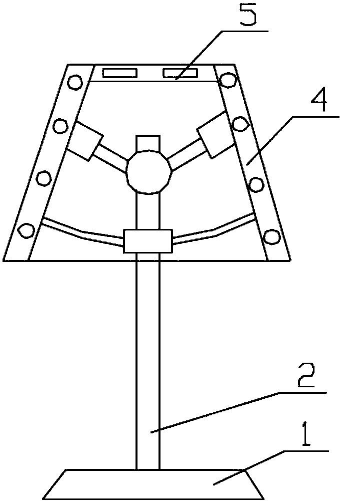
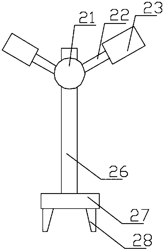
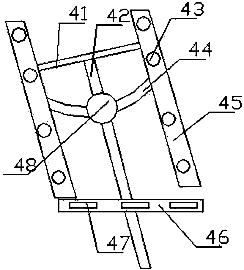
[0024] Such as Figure 1 to Figure 3 As shown, the LED lighting provided by the present invention includes a base 1, and also includes a lamp holder 2 screwed to the upper end of the base 1 through a screw thread, and a second lamp holder clamped to the outer side of the upper end of the lamp holder 2. A group of lamps 4 and a third group of lamps 5 that is clamped to the upper end of the second group of lamps 4;
[0025] The lamp holder 2 includes a central support rod 26, a fixing plate 27 screwed to the lower end of the central support rod 26 through threads, a first clamping pin 28 that is clamped at the edge of the lower end of the fixing plate 27, The integrated ball 21 screwed to the upper end of the central support rod 26 by threads, the first telescopic rod 22 clamped on the outer wall of the integrated ball 21 along the radial direction of the integrated ball 21 and the The axial direction of the first telescopic rod 22 is sleeved on the first telescopic cylinder 23 at the end of the first telescopic rod 22;
[0026] The second group of lamps 4 includes a lamp pole 42, an internal integrated ball 48 screwed on the lamp pole 42 through a thread, a beam 41 clamped on the upper end of the lamp pole 42, and a beam 41 clamped to the beam 41. The third lamp tube 45 at the end of the inner integrated ball 48 passes through the inner integrated ball 48 along the radial direction of the inner integrated ball 48, and the end is clamped on the side wall of the third lamp 45. A connecting rod 44, a spherical LED lamp 43 clamped in the third lamp tube 45, a fourth lamp tube 46 clamped to the lower part of the lamp pole 42 and at the lower end of the third lamp tube 45, and The rectangular LED lamp 47 in the fourth lamp tube 46 is clamped.
[0027] Further, the fixed disk 27 is in the shape of a disc, a first screw connection groove is recessed in the upper part of the fixed disk 27, and a thread is provided in the spiral recess in the first screw connection groove. The screw groove is compatible with the central support rod 26; the central support rod 26 is round rod-shaped;
[0028] The integrated ball 21 has a spherical shape, and a first clamping and fixing hole is penetrated therein along the radial direction of the integrated ball 21, and the first clamping and fixing hole is compatible with the first telescopic rod 22; The first telescopic rod 22 is in the shape of a round rod; the first telescopic tube 23 is cylindrical, and a first guide hole is penetrated therein along the axial direction of the first telescopic tube 23. The guide hole is adapted to the first telescopic rod 22; the two first telescopic rods 22 are symmetrical with respect to the central support rod 26.
[0029] Further, the inner integrated ball 48 is spherical, and a first screw fixing hole is pierced therein along the radial direction of the inner integrated ball 48, and a spiral concave is formed in the first screw fixing hole. There is a thread, the first screw fixing hole is adapted to the light pole 42; the light pole 42 is a round rod; along the radial direction of the inner integrated ball 48, a first fixing hole is inserted into it. Hole, the first fixing hole is compatible with the first connecting rod 44; the first connecting rod 44 is in the shape of an arc; the beam 41 is in the shape of a round rod;
[0030] The third lamp tube 45 has a circular tube shape, a second mounting hole is penetrated in the side wall of the third lamp tube 45, and the second mounting hole is adapted to the beam 41; the first connection The rod 44 is arc-shaped; a first fixing groove is recessed on the side wall of the third lamp tube 45, and the first fixing groove is adapted to the first connecting rod 44; The third lamp tubes 45 are respectively located on both sides of the lamp pole 42;
[0031] The fourth lamp tube 46 has a circular tube shape, and a first lamp installation groove is recessed in the fourth lamp tube 46, and the first lamp installation groove is compatible with the rectangular LED lamp 47; The rectangular LED lights 47 are evenly distributed along the length direction of the fourth tube 46;
[0032] The third group of lamps 5 includes a main lamp tube and a third LED lamp clamped in the main lamp tube; a second lamp installation groove is formed between the upper ends of the two second group lamps 4, the The second lamp installation slot is compatible with the third group of lamps 5.
[0033] The above shows and describes the basic principles, main features and advantages of the present invention. Those skilled in the industry should understand that the present invention is not limited by the above-mentioned embodiments. The above-mentioned embodiments and the description only illustrate the principles of the present invention. The present invention will have various aspects without departing from the spirit and scope of the present invention. Various changes and improvements, these changes and improvements fall within the scope of the claimed invention. The scope of protection claimed by the present invention is defined by the appended claims and their equivalents.

PUM

no PUM

Description & Claims & Application Information

We can also present the details of the Description, Claims and Application information to help users get a comprehensive understanding of the technical details of the patent, such as background art, summary of invention, brief description of drawings, description of embodiments, and other original content. On the other hand, users can also determine the specific scope of protection of the technology through the list of claims; as well as understand the changes in the life cycle of the technology with the presentation of the patent timeline. Login to view more.
Why Eureka
Try Eureka