Lens module for LED light sources

Inactive Publication Date: 2014-05-08
GENIUS ELECTRONICS OPTICAL CO LTD
View PDF3 Cites 9 Cited by
  • Summary
  • Abstract
  • Description
  • Claims
  • Application Information

AI Technical Summary

Benefits of technology

[0017]Wherein, the light exiting surface further comprises a connection portion in the periphery. The connecting portion allows the curved surface design of the light exiting surface to achieve a desired light distribution, while also allows the size of the lens body to satisfy standard requirements
[0018]As set forth above, the exemplary embodiments of the pre

Problems solved by technology

However, comparing to conventional light sources, LED has a smaller light divergence angle and thus light emitted therefrom is more concentrated, causing brightness differences between the central section and the peripheral section of the illuminated area; that is, the light source may not have uniform illumination.
However, road lamps are g

Method used


Image

  • Lens module for LED light sources
  • Lens module for LED light sources
  • Lens module for LED light sources

Examples


first embodiment

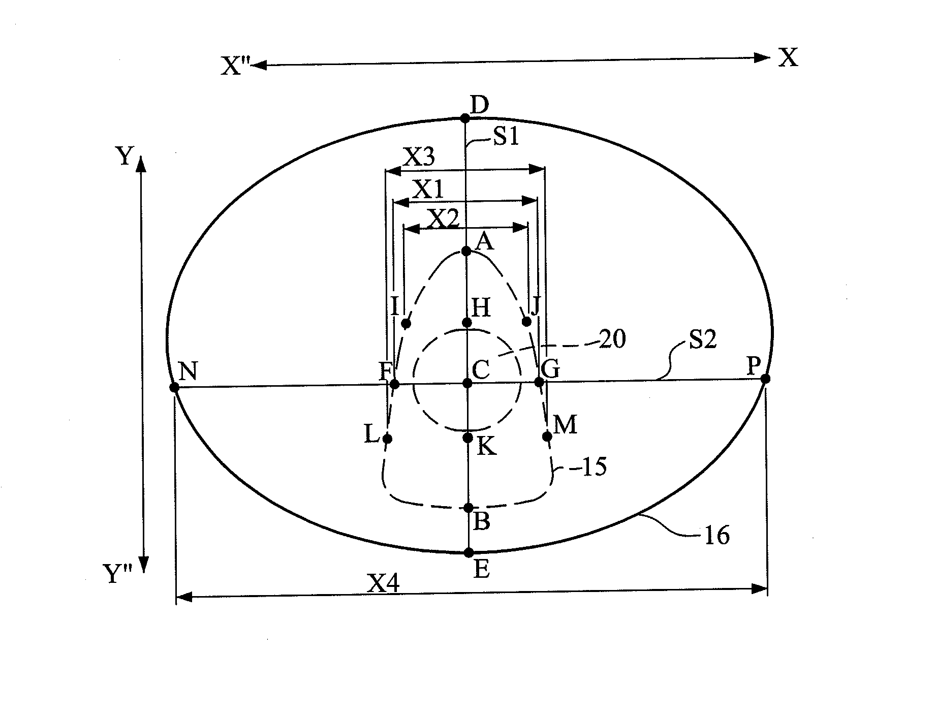
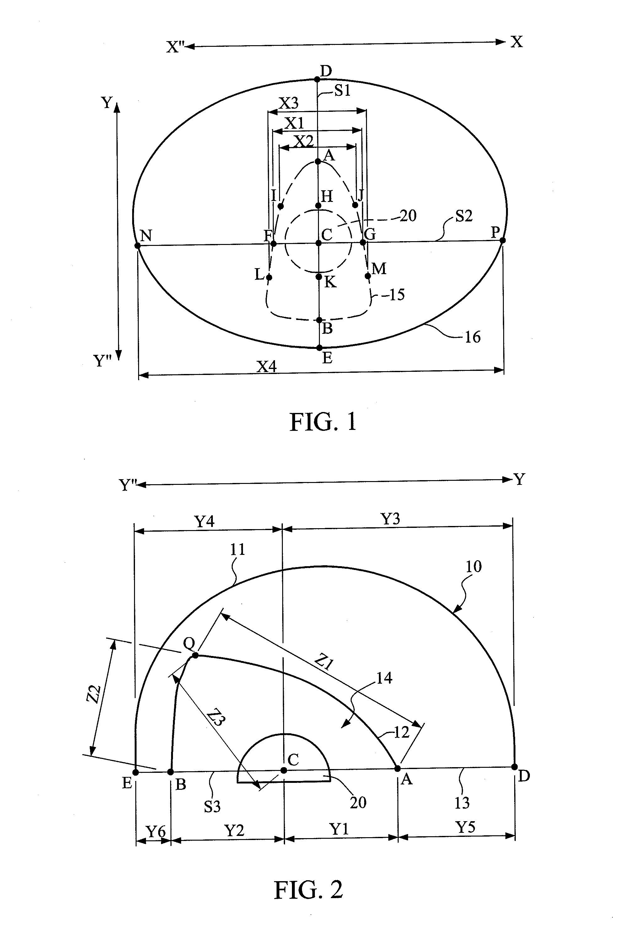
[0040]In implementing the Y1=3.1 mm and Y2=3.0 mm, wherein Y1 denotes the minimum distance between the point A and the point C, and Y2 denotes the minimum distance between the point B and the point C; Z1=6.2 mm and Z2=3.1 mm, wherein Z1 denotes the minimum distance between the point A and the point Q, and Z2 denotes the minimum distance between the point B and the point Q; Z3=3.8 mm, wherein Z3 denotes the minimum distance between the point C and the point Q; Y3=6.2 mm and Y4=4.0 mm, wherein Y3 denotes the minimum distance between the point C and the point D, and Y4 denotes the minimum distance between the point C and the point E; Y5=3.1 mm and Y6=1.0 mm, wherein Y5 denotes the minimum distance between the point A and the point D, and Y6 denotes the minimum distance between the point B and the point E; X2=2.7 mm, X1=3.4 mm and X3=3.7 mm, wherein X1 denotes the minimum distance between the point F and the point G, X2 denotes the minimum distance between the point I and the point J, ...

second embodiment

[0046]In implementing the Y1=2.0 mm and Y2=3.0 mm; Z1=4.5 mm, Z2=3.0 mm and Z3=3.5 mm; Y3=7.0 mm and Y4=4.0 mm; Y5=5.0 mm and Y6=1.0 mm; X1=3.0 mm, X2=2.5 mm and X3=3.5 mm; and X4=13.8 mm, wherein X4 / X1=4.6, and Y5 / (Y3+Y4)=0.45.

[0047]In the present embodiment, the following conditions are satisfied: Z1>Z2, Z3>Y1, Y3>Y4, Y5>Y6, X21≦X3, and Y2>Y1. Further, the maximum length of the light exiting surface 11 on the reference surface S3 is 14.5 mm, and the vertical distance between the highest point of the light exiting surface 11 and the reference surface S3 is 5.5 mm.

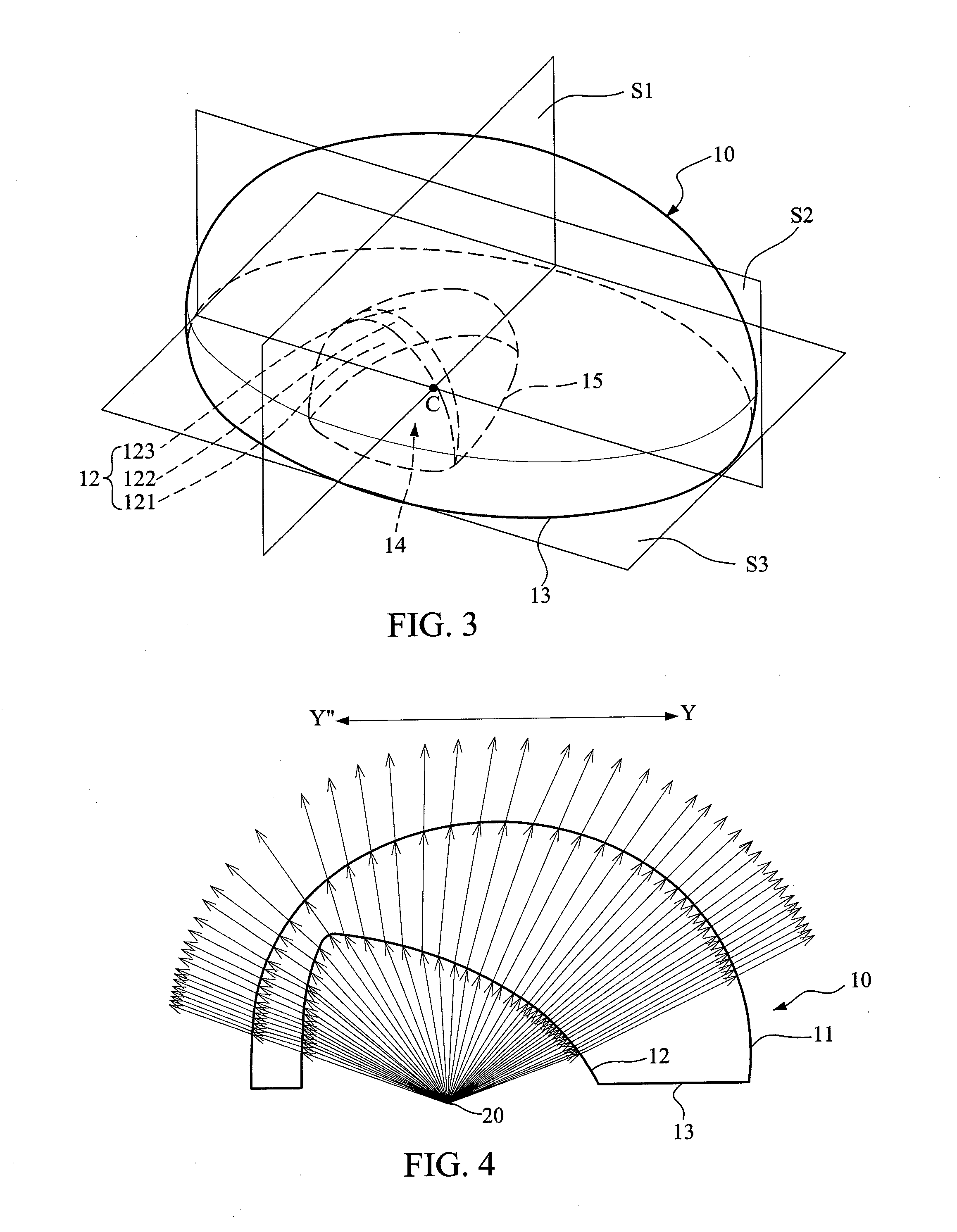
[0048]Please further refer to FIG. 9, which is a view illustrating the lights according to the second embodiment of the present invention. As shown in FIG. 9, the light emitted from the LED light source 20 is refracted by the light incident surface 12 and the light exiting surface 11 of the lens body 10; this may deflect most of the light to the Y side.

[0049]FIG. 10 is a contour map illustrating the light distribution acc...

third embodiment

[0051]In implementing the Y1=2.2 mm and Y2=5.0 mm; Z1=5.5 mm, Z2=3.5 mm and Z3=4.0 mm; Y3=7.5 mm and Y4=6.5 mm; Y5=5.3 mm and Y6=1.5 mm; X1=6.5 mm, X2=5.0 mm and X3=8.0 mm; and X4=14.5 mm, wherein X4 / X1=2.23, and Y5 / (Y3+Y4)=0.38.

[0052]In the present embodiment, the following conditions are satisfied: Z1>Z2, Z3>Y1, Y3>Y4, Y5>Y6, X21≦X3, and Y2>Y1. Further, the maximum length of the light exiting surface 11 on the reference surface S3 is 14.5 mm, and the vertical distance between the highest point of the light exiting surface 11 and the reference surface S3 is 8.0 mm.

[0053]Please further refer to FIG. 14, which is a view illustrating the lights according to the third embodiment of the present invention. As shown in FIG. 14, the light emitted from the LED light source 20 is refracted by the light incident surface 12 and the light exiting surface 11 of the lens body 10; this may deflect most of the light to the Y side.

[0054]FIG. 15 is a contour map illustrating the light distribution a...


PUM


Abstract

A lens module for LED light sources including: a lens body; and an LED light source received in a recess of the lens body. By the conditions of Z1>Z2 and Z3>Y1, and with the shape of light incident surface and the position of LED light source, a light deflection effect is achieved. This allows light emitted from the LED light source to be refracted by the light incident surface and then emitted by the light exiting surface, generating an excellent light deflection effect, thereby increasing illumination in width at the road or public squares and increasing utilization rate of the LED light source.

Description

CROSS-REFERENCE TO RELATED APPLICATION[0001]This application claims priority from Taiwan Patent Application No. 101128789, filed on Aug. 9, 2012, the contents of which are hereby incorporated by reference in their entirety for all purposes.BACKGROUND[0002]1. Field of the Invention[0003]The present invention relates to a lens module for LED light sources, and more particularly to a lens module capable of shifting illumination areas.[0004]2. Brief Description of the Related Art[0005]Recently, considering the requirements of energy-saving and environmental protection, lighting equipment manufacturers and research units gradually employ light emitting diodes (LED) as light sources in lighting equipment. The LED is a solid semiconductor device that can convert electrical energy directly into light. The LED has advantages such as small volume, short response time, low power consumption, and low contamination.[0006]However, comparing to conventional light sources, LED has a smaller light d...

Claims


Application Information

Patent Timeline
IPC IPC(8): F21V5/04
CPCF21V5/08F21V5/04F21Y2101/02G02B19/0061G02B19/009G02B3/00F21W2131/103F21Y2115/10
Inventor LIN, YI-JIEWU, CHIH-CHIEHHO, YEN-WEI
Owner GENIUS ELECTRONICS OPTICAL CO LTD
Why Eureka
Try Eureka