Light Source Device And Display Device

A technology for display devices and light source devices, which is applied in the direction of light sources, electric light sources, lighting devices, etc., can solve the problems of reflective sheet wrinkles, deterioration of optical characteristics of liquid crystal display devices, etc., and achieve the effect of dispersing brightness decline and suppressing uneven brightness

Inactive Publication Date: 2012-04-25
SHARP KK
View PDF10 Cites 9 Cited by
  • Summary
  • Abstract
  • Description
  • Claims
  • Application Information

AI Technical Summary

Problems solved by technology

[0029] However, in the LED-type backlight device described in Patent Document 2, there is a problem that, when the reflective sheet fixed to one surface of the light-emitting diode substrate with screws expands and contracts due to sudden thermal changes, the Stretching causes wrinkles on the reflective sheet, deteriorating the optical characteristics of the liquid crystal display device

Method used


Image

  • Light Source Device And Display Device
  • Light Source Device And Display Device
  • Light Source Device And Display Device

Examples


Embodiment approach 1-1

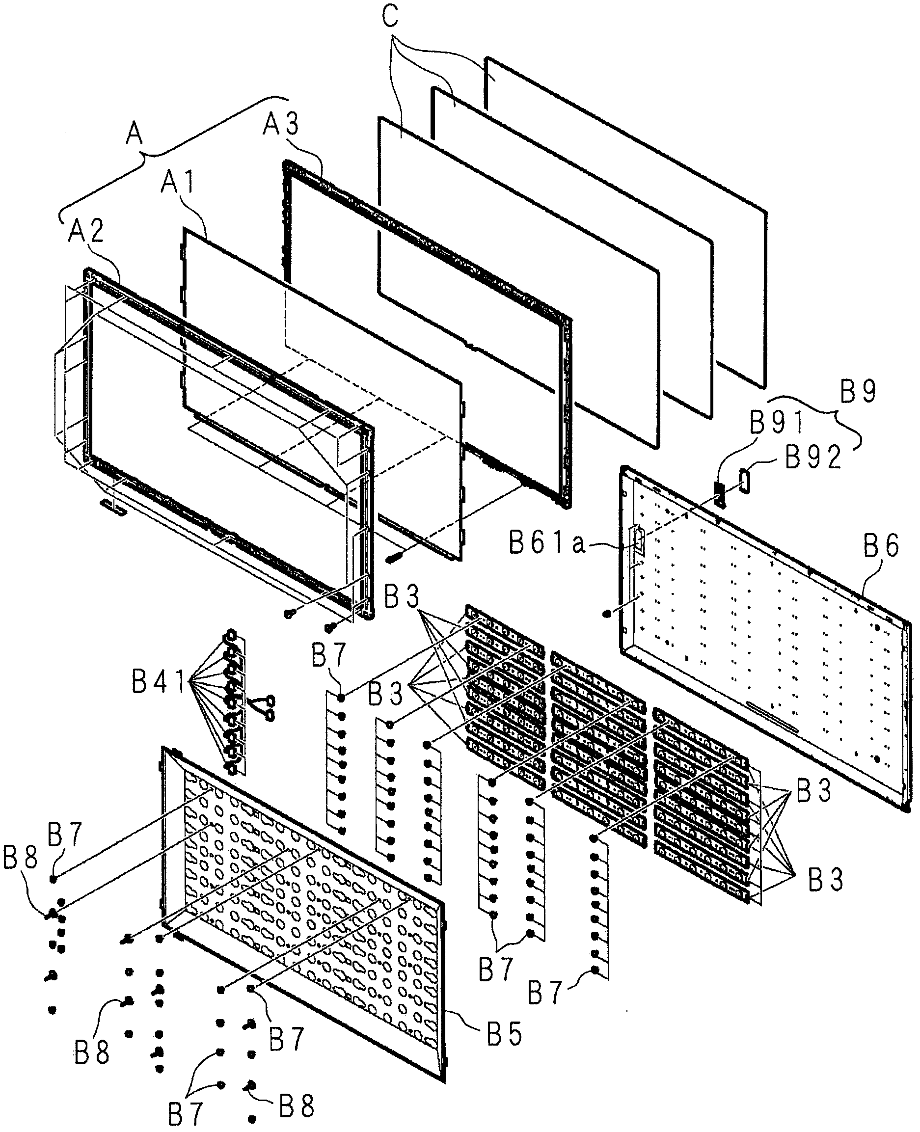
[0315] Figure 29 Is a perspective view showing the structure of the light source device according to the present invention, Figure 30 Is a plan view showing the structure of the light source device, Figure 31 It is a plan view showing the structure obtained by omitting the reflection sheet of the light source device, Figure 32 It is an enlarged cross-sectional view of a part showing the structure of the light source device.

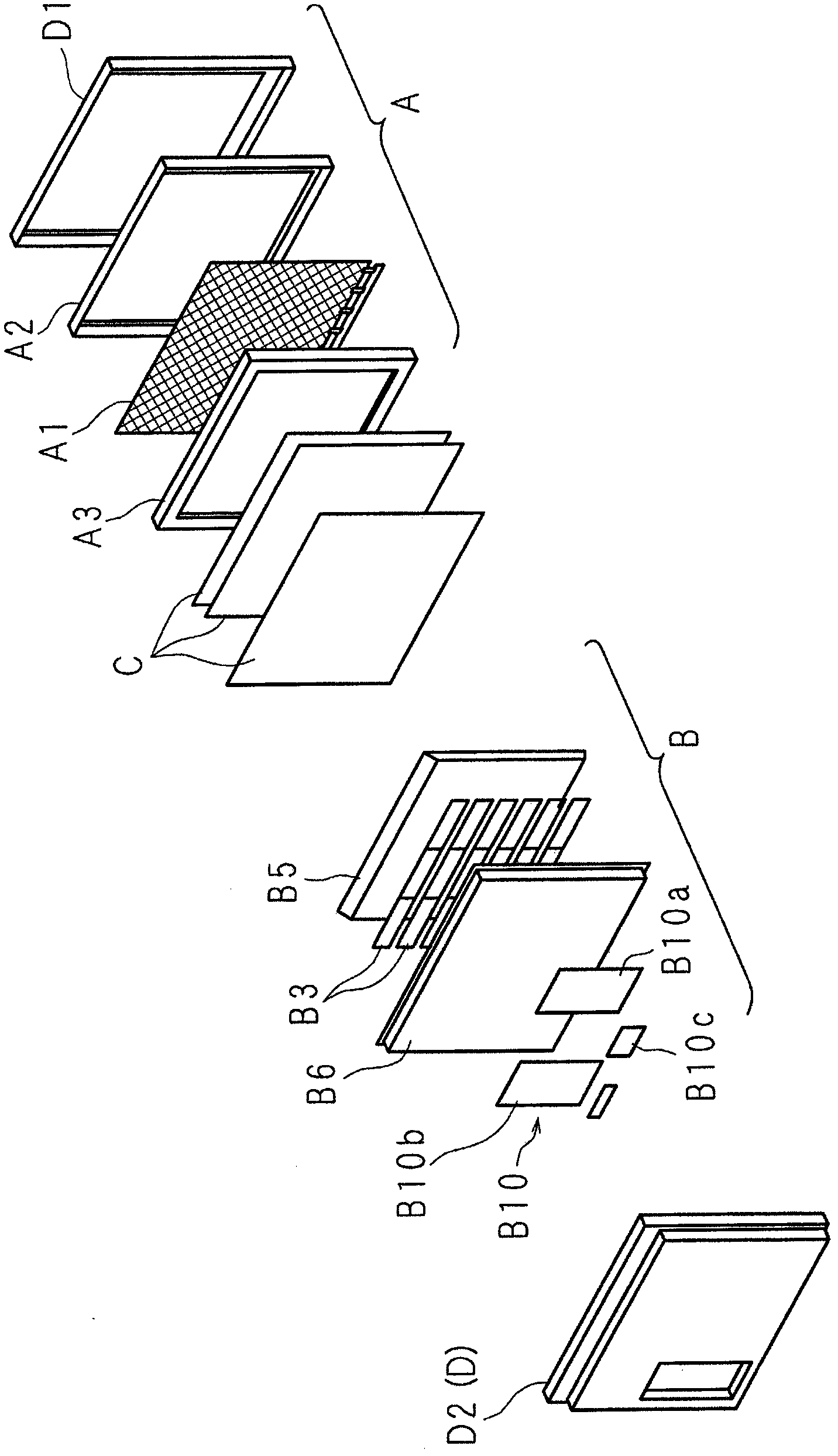
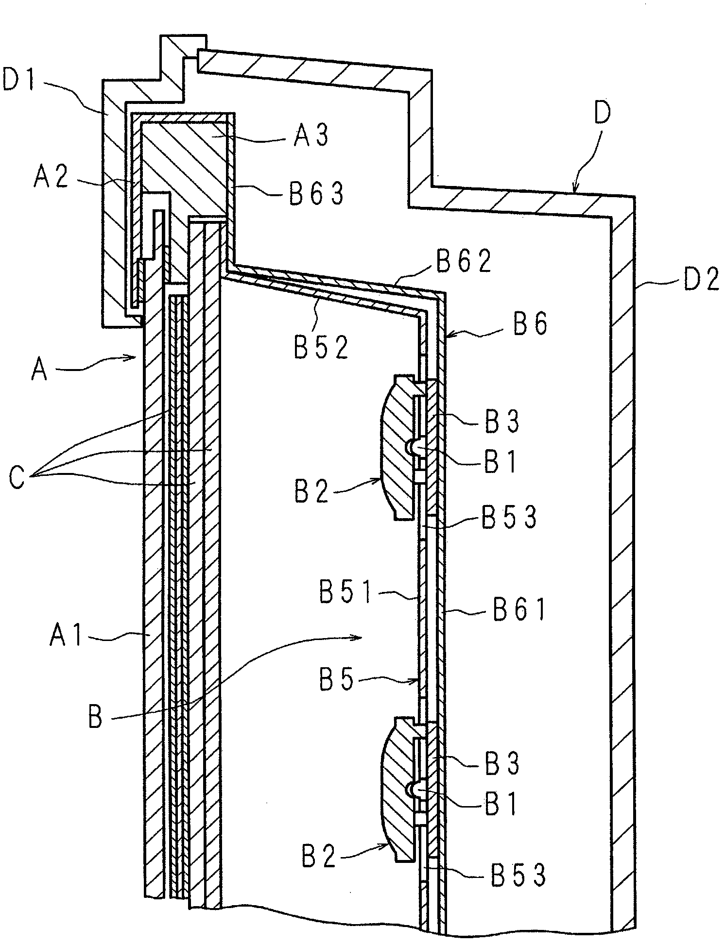
[0316] The light source device (B) shown in the figure is mounted on the back side of the display portion in a thin display device equipped with a display portion (A). The display portion (A) is substantially rectangular and has a display surface on the front side. The light source device (B) includes: a plurality of light-emitting diodes 1 (B1), the plurality of light-emitting diodes 1 (B1) as light sources are arranged side by side in a grid shape; a plurality of light-emitting diode substrates 2 (B3), the plurality of light-emitting diode substrates 2 ...

Embodiment approach 1-2

[0337] Figure 38 It is an exploded front view showing another configuration of the main part of the reflection sheet included in the light source device according to the present invention. The light source device adopts the following structure: that is, a substantially V-shaped cutout 57 is provided at the corner 52a of the frame part 52, instead of providing three second strips at the corner of the frame part 52 of the reflection sheet 5 (B5). The fold line 53, when the four frame parts 52 connected to the four sides of the flat part 51 are bent in an oblique shape with respect to the flat part 51 at the first fold line 5b, the two edge parts 57a, 57a of the cutout part 57 Put them together, and use the double-sided tape 55 to keep the put together.

[0338] The reflective sheet 5 formed of a rectangular synthetic resin sheet material has a flat portion 51 that is smaller than the plate portion 61 of the support housing 6, and is connected to the four sides of the flat portion ...

Embodiment approach 1-3

[0341] Figure 39 It is an exploded front view showing another configuration of the main part of the reflection sheet included in the light source device according to the present invention, Figure 40 It is an enlarged front view showing the other structure of the main part of the reflection sheet. The light source device adopts the following structure: that is, three second fold lines 53 extending from the corner 51a of the flat portion 51 of the reflective sheet 5 to the periphery of the frame portion 52 and a cutout 58 are provided instead of the reflective sheet 5 The corner 52a of the frame part 52 is provided with a cutout 57, the corner 52a of the frame part 52 is formed by the second fold line 53, and the ends of the adjacent frame part 52 are joined together by the cut 58. The double-sided tape maintains the state and the corners 52a put together.

[0342] The cutouts 58 are provided to extend from the corners 51a of the flat portion 51 along the opposite sides of the fl...


PUM


Abstract

There are provided a light source device and a display device which do not generate a wrinkle on an optical sheet even if the optical sheet is held on an LED substrate. A reflection sheet 11 is disposed between each of head portions possessed by a rivet, a positioning rivet and a support rivet and one surface of an LED substrate 8 where an LED is mounted, and a gap in a direction of a sheet thickness is provided between the head portion of each of the rivets and the reflection sheet 11. In the case in which a sudden thermal change is caused, therefore, the reflection sheet 11 expands or contracts between the head portion of each of the rivets and the reflection sheet 11 so that the wrinkle can be prevented from being generated over the reflection sheet 11.

Description

Technical field [0001] The present invention relates to a light source device provided with a light emitting element, and a display device equipped with the light source device to display video. Background technique [0002] So-called thin liquid crystal display devices such as liquid crystal televisions include a substantially rectangular parallelepiped display portion having a display surface for displaying images on the front side, and a light source device arranged on the back side of the display portion to irradiate the display portion with light. Between the device and the display unit, optical sheets such as a diffuser plate and a prism sheet are arranged. [0003] The display unit has a liquid crystal display panel having a substantially rectangular parallelepiped. Since the liquid crystal display panel itself cannot emit light, an illuminating light source for displaying video on the display surface is required, and a backlight device is used as the illuminating light sou...

Claims


Application Information

Patent Timeline
Patent Type & Authority Applications(China)
IPC IPC(8): F21S2/00F21V17/00G02F1/13357F21Y101/02
Inventor 竹内秀仁藤田稔之菅原达夫川村优贵谷畑守高桥洋伊藤启太岁行健藏伊东贤一郎中道一喜佐佐木智雄守部研太
Owner SHARP KK
Why Eureka
Try Eureka