Light emitting indicator

A technology of luminous pointers and pointers, which is applied in the direction of measurement value indication, instruments, and measuring instrument components. The effect of the amount of light supplied

Inactive Publication Date: 2005-07-27
NIPPON SEIKI CO LTD
View PDF0 Cites 0 Cited by
  • Summary
  • Abstract
  • Description
  • Claims
  • Application Information

AI Technical Summary

Problems solved by technology

[0006] However, when installing a filter component to make the light-emitting surface evenly emit light, since the configuration position of the filter component is relatively close to the light-emitting surface, sometimes the shadow of the filter component appears at the position of the light-emitting surface corresponding to the filter component. detrimental to commodity
[0007] In addition, when the light-shielding pole is used to limit the introduced illumination light, due to the existence of the light-shielding plate, the introduction path of the illuminating light is limited to the part corresponding to the reflection part passing through the hole, so the light-emitting surface located in the rotation center area covered by the light-shielding plate The area becomes dark, and it is difficult to obtain uniform light emission on the light emitting surface
Especially when there is a reflector at a position away from the light-emitting surface to the side, the brightness of the light-emitting surface located in the rotation center area is likely to be insufficient.

Method used


Image

  • Light emitting indicator
  • Light emitting indicator
  • Light emitting indicator

Examples


Embodiment Construction

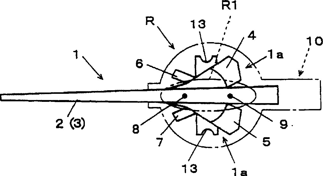
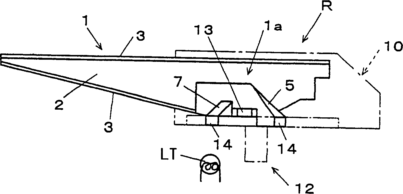
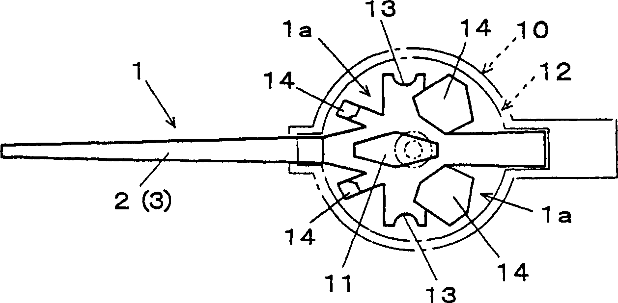
[0016] Figure 1(a) to Figure 1(c) Among them, the pointer body 1 is made of translucent resin materials such as acrylic ester and polycarbonate, and extends in a straight line, and the front side and the back side of the indicator part 2, which constitutes the light-emitting surface described later, are formed by hot-pressed foil. Colored part 3 composed of layers.

[0017] The pointer body 1 (indicating part 2) is driven by a pointer shaft not shown in the figure, and several reflection parts 4-7 are formed in the rotation center region R connected to the pointer shaft and covered by a rear light-shielding cover. These reflecting parts receive the illumination light from the external light source LT at the back, and form the front side of the indicator part 2 as a light emitting surface that continuously emits light from the front end side to the rear end side.

[0018] These reflectors 4 to 7 utilize the protruding portion 1a protruding from the indicator 2 to both sides w...


PUM


Abstract

The invention provides a luminous pointer which can offer an increased commercial value with its glowing surface having the ability to glow generally uniformly. The luminous pointer is constructed of a pointer element 1 which is made of a light-transmitting material and forms an indicating portion (glowing surface) 2, a light-blocking cover 10 which covers a central region of swing motion R of the pointer element 1 and opens rearward, and a shielding element 12 which covers the rear side of the central region of swing motion R of the pointer element 1. The pointer element 1 has in its central region of swing motion R reflecting parts 4 to 7 for reflecting illuminating light fed from the rear side at least toward its tip end, and the shielding element 12 has exposing parts 123 for exposing the reflecting parts 4 to 7 of the pointer element 1 and is formed of a light-transmitting material which makes it possible to adjust the amount of transmission of the illuminating light.

Description

technical field [0001] The present invention relates to a light-emitting pointer used in various instruments, and more particularly to a light-emitting pointer that emits light in a linear shape by introducing illumination light from a rotating center. Background technique [0002] In the prior art, this kind of luminous pointer is to guide the light emitted by an external light source into the pointer body made of transparent material, so that it emits light in a linear shape. [0003] Specifically, for example, in the rotation center area of ​​the pointer body made of transparent resin materials such as acrylic ester and polycarbonate, a reflection part that reflects the illumination light to the end is provided, and a light-shielding cover (formed on the light-shielding cover) is used. There is a slit that exposes the light-emitting surface part) to cover the rotation center area of ​​the pointer body including the reflection part, and the illumination light introduced in...

Claims


Application Information

Patent Timeline
Patent Type & Authority Patents(China)
IPC IPC(8): G01D11/28G01D13/28
CPCG01D13/28G01D11/28
Inventor 五十岚秀树
Owner NIPPON SEIKI CO LTD
Why Eureka
Try Eureka