
Backlight and liquid crystal display device

A technology of backlight and light source, which is applied in the direction of electric light source, lighting device, fixed lighting device, etc. It can solve the problems of uneven brightness in oblique direction, uneven brightness, and damage to the uniformity of the picture, and achieve the suppression of uneven brightness in the front and oblique Towards brightness unevenness, the effect of suppressing brightness unevenness

Inactive Publication Date: 2013-02-13
SONY CORP
View PDF1 Cites 0 Cited by
  • Summary
  • Abstract
  • Description
  • Claims
  • Application Information

AI Technical Summary

Problems solved by technology

[0017] (2) Disadvantage 2 (occurrence of uneven brightness in oblique direction)
[0020] (3) Disadvantage 3 (Visibility of stud pins)
[0021] Due to the removal of the diffuser between the shaped diffuser and the prism sheet, the degree of diffusion is reduced, so multiple stud pins supporting the optical sheet (shaped diffuser) are visible, disrupting the uniformity of the picture
[0022] (4) Disadvantage 4 (uneven brightness caused by size error of backlight source)
[0027] Also, as mentioned above, if the diffusion sheet is simply removed from the existing configuration, brightness unevenness will occur due to insufficient diffusion.
Therefore, if a diffusing agent is added to the entire shaped diffuser (both the lens portion and the base) to improve such brightness unevenness, the brightness will decrease.

Method used


Image

  • Backlight and liquid crystal display device
  • Backlight and liquid crystal display device
  • Backlight and liquid crystal display device

Examples


no. 1 approach

[0112] 1. First embodiment (an example of improving uneven brightness by using a prism sheet)

[0113] 2. Second embodiment (an example of improving uneven brightness by a diffuser)

no. 3 approach

[0114] 3. Third embodiment (an example of improving uneven brightness by a combination of a prism sheet and a diffusion sheet)

[0115] 4. Fourth embodiment (an example of a shaped diffusion plate of a single-layer structure, a backlight including the shaped diffusion plate, and a liquid crystal display device)

no. 5 approach

[0116] 5. Fifth embodiment (an example of a shaped diffuser having a multilayer structure)

[0117] 1. The first embodiment

[0118] (Configuration of liquid crystal display device)

[0119] Figure 4 It is a schematic diagram of a configuration example of the liquid crystal display device according to the first embodiment of the present invention. Such as Figure 4 As shown, the liquid crystal display device includes a backlight 1 that emits light and a liquid crystal panel 2 that modulates the light emitted from the backlight 1 in time and space and displays an image.

[0120] Hereinafter, the liquid crystal panel 2 and the backlight 1 included in the liquid crystal display device will be described in order.

[0121] (LCD panel)

[0122] The liquid crystal panel 2 can use, for example, a twisted nematic (TN) mode, a super twisted nematic (STN) mode, a vertical array (VerticaLLy ALigned: VA) mode, and a horizontal array (In-PLane Switching: IPS) mode. Mode, Optical Compensated Birefri...


PUM

PropertyMeasurementUnit
angleaaaaaaaaaa
angleaaaaaaaaaa
diameteraaaaaaaaaa

Abstract

A diffusion plate includes a base body including a plurality of convex portions formed on a principal surface of the base body. An angle of inclination of the convex portions at a base of the convex portions ranges from 38° to 42°. Also, a ratio R / Cp between a curvature R of a summit of the convex portions and a pitch Cp between adjacent convex portions is 0.0014<R / Cp<0.43.

Description

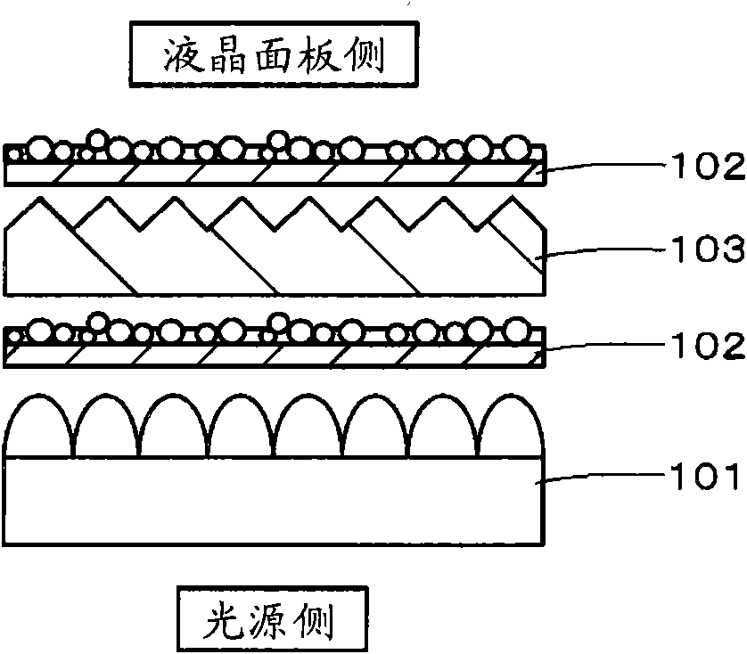
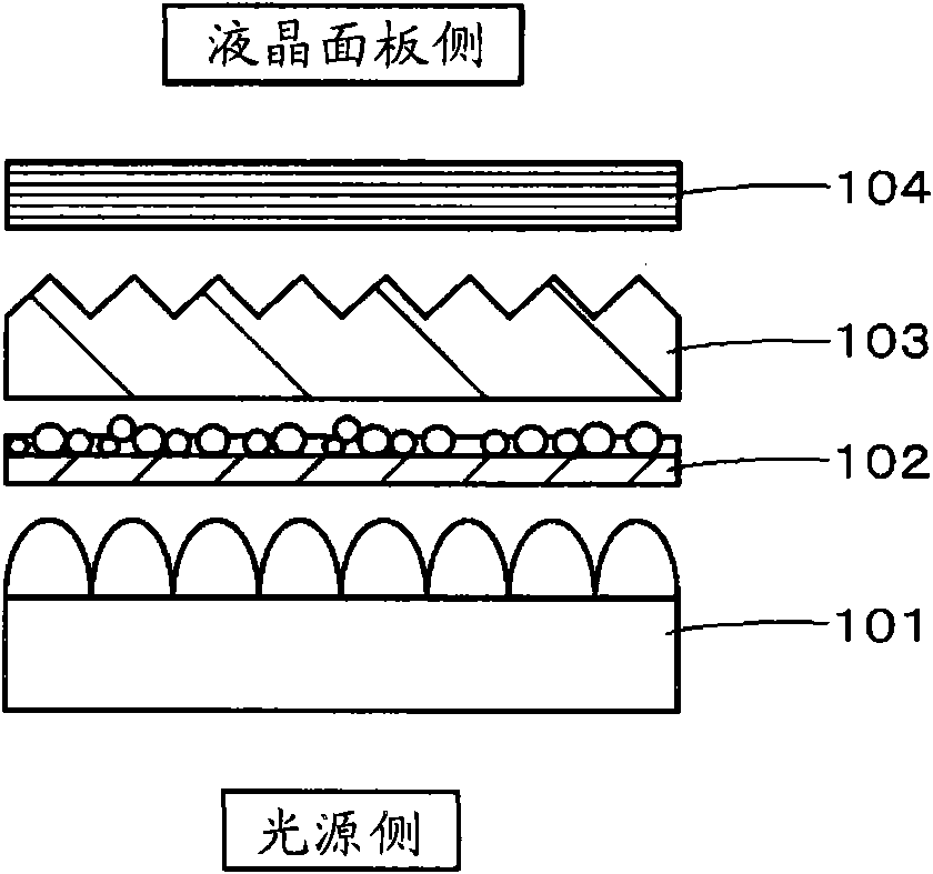
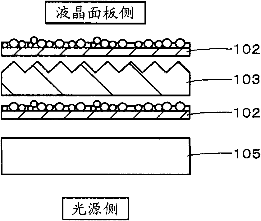
Technical field [0001] The present invention relates to a backlight source and a liquid crystal display device including the backlight source. Specifically, it relates to a backlight that can suppress uneven brightness. In addition, the present invention relates to a diffuser containing a diffuser, a backlight including the diffuser, and a liquid crystal display device. Background technique [0002] Since the liquid crystal display device is not a self-luminous display device, a backlight is arranged behind it. Backlight methods can be divided into two categories, edge-lit and direct-lit. Direct-lit backlights are widely used in large LCD TVs that require high brightness. [0003] The conventional direct type backlight is a sheet laminate in which a plurality of optical sheets are laminated between the light source and the liquid crystal panel. Such as Figure 1A to Figure 1C As shown, the structure of the laminated body generally adopts the following three structures. [0004] Co...

Claims


Application Information

Patent Timeline
Patent Type & Authority Patents(China)
IPC IPC(8): G02F1/13357
CPCG02B5/0226F21V5/02G02B5/0242F21V3/00G02B5/02G02F2001/133607G02B5/0247G02B5/0215F21S8/00F21S2/00G02F1/133607
Inventor 新开章吾太田荣治工藤泰之播磨龙哉林沙织
Owner SONY CORP
Learn More