Antenna device and display device including the same
An antenna device, antenna pattern technology, applied in the direction of antenna grounding device, antenna support/mounting device, antenna, etc., can solve the problem of not considering the degradation of antenna image, achieve the purpose of suppressing electrode visibility, improving performance, and preventing moiré The effect of the phenomenon
- Summary
- Abstract
- Description
- Claims
- Application Information
AI Technical Summary
Problems solved by technology
Method used
Image
Examples
Embodiment approach
[0036] According to an exemplary embodiment of the present invention, there is also provided a display device including the antenna device. Applications of the antenna device are not limited to display devices, and the antenna device may be applied to various objects or structures such as vehicles, home appliances, buildings, and the like.
[0037] Hereinafter, the present invention will be described in detail with reference to the accompanying drawings. However, those skilled in the art will appreciate that such embodiments described with reference to the accompanying drawings are provided for further understanding of the spirit of the present invention and do not limit the subject matter to be protected as disclosed in the detailed description and the appended claims.
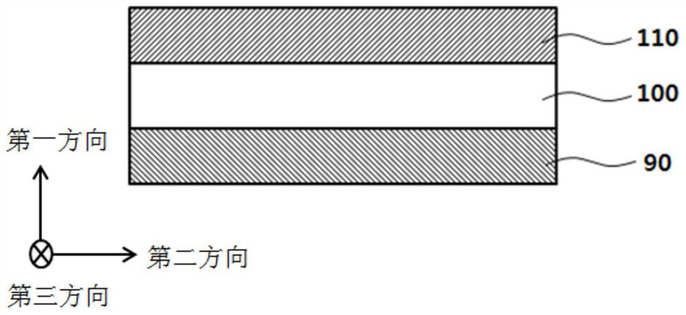
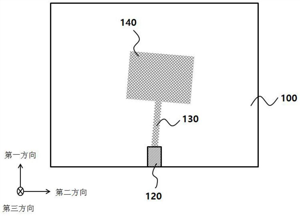
[0038] figure 1 with figure 2 are a schematic cross-sectional view and a schematic top plan view showing an antenna device according to an exemplary embodiment, respectively.
[0039] refer to figure 1 w...
Embodiment 1
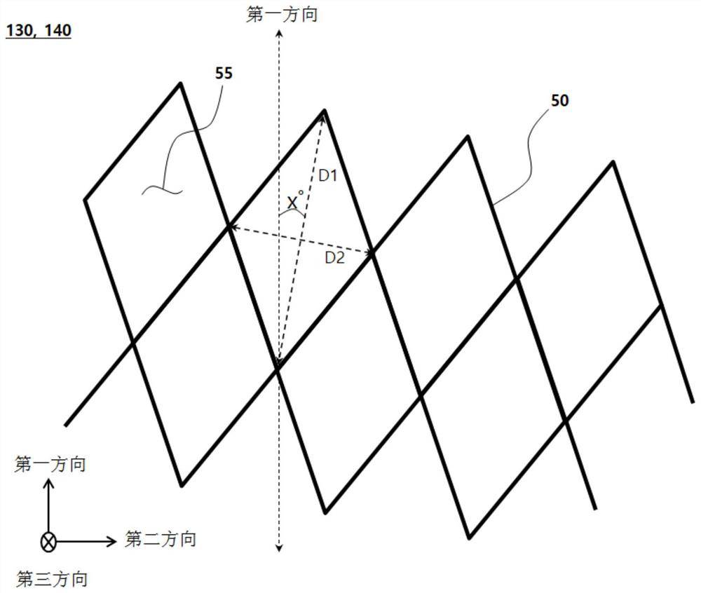
[0094] On the top surface of the glass dielectric layer (0.7T), an alloy (APC) of silver (Ag), palladium (Pd), and copper (Cu) is used to form radiation patterns and transmission lines having a grid structure. The wires included in the mesh structure are formed to have a line width of 2.5 μm and The thickness (or height) of , and the grid structure is formed with rhombus-shaped unit cells. The length of the X-axis diagonal (short diagonal) of the diamond-shaped unit cell is 150 μm, and the length of the Y-axis diagonal (long diagonal) is 250 μm.
[0095] The long diagonals of the diamond-shaped unit cells of the mesh structure were formed to be inclined at an angle of 2° with respect to the first direction (Y-axis direction).
Embodiment 2
[0097] The antenna device was formed by the same method as in Embodiment 1, except that the long diagonals of the rhombic unit cells of the mesh structure were formed to be inclined at an angle of 10° with respect to the first direction (Y-axis direction).
PUM
 Abstract
Description
Claims
Application Information
 - R&D
- Intellectual Property
- Life Sciences
- Materials
- Tech Scout
- Unparalleled Data Quality
- Higher Quality Content
- 60% Fewer Hallucinations
Browse by: Latest US Patents, China's latest patents, Technical Efficacy Thesaurus, Application Domain, Technology Topic, Popular Technical Reports.
© 2025 PatSnap. All rights reserved.Legal|Privacy policy|Modern Slavery Act Transparency Statement|Sitemap|About US| Contact US: help@patsnap.com


