

Method for controlling transmitting power and mobile terminal
A technology of transmission power control and transmission power, which is applied in the field of communication and can solve problems such as signal interference
- Summary
- Abstract
- Description
- Claims
- Application Information
AI Technical Summary
Problems solved by technology
Method used
Image

Examples
no. 1 example
[0020] Such as image 3 As shown, it is a schematic flow chart of the method for transmitting power control provided by the first embodiment of the present invention, which is applied to a mobile terminal including a first radio frequency transceiver module and a second radio frequency transceiver module. The method includes:
[0021] Step 301, according to the acquired working frequency information of the first radio frequency transceiver module, judge whether the working frequency information of the first radio frequency transceiver module satisfies a preset interference condition;
[0022] In the embodiment of the present invention, the working frequency information of the above-mentioned first radio frequency transceiver module can be understood as a working frequency band or working frequency point, and the working frequency band or working frequency point of the first radio frequency transceiver module can realize signal transceiving. The above preset interference condit...
no. 2 example
[0032] Such as Figure 4 As shown, it is a schematic structural diagram of the mobile terminal provided by the second embodiment of the present invention. The mobile terminal 400 includes a first radio frequency transceiver module 401, a second radio frequency transceiver module 402, and the first radio frequency transceiver module 401 and the second radio frequency transceiver module 401. The antenna 403 connected to the radio frequency transceiver module 402 also includes:
[0033] A switching module 404, one end is connected to the second radio frequency transceiver module 402 and the other end is connected to the antenna 403, and is used to form a signal power attenuation process between the second radio frequency transceiver module 402 and the antenna 403. The first signal transceiving channel and the second signal transceiving channel without attenuation processing, and switching the second radio frequency transceiving module 402 to transmit signals to the antenna 403 th...
no. 3 example
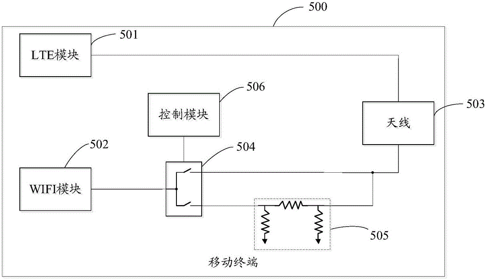
[0046] This embodiment is described by taking the first radio frequency transceiver module as an LTE module and the second radio frequency transceiver module as a WIFI module in the mobile terminal as an example. Such as Figure 5 As shown, it is a schematic structural diagram of a mobile terminal provided by the third embodiment of the present invention. The mobile terminal 500 includes an LTE module 501 , a WIFI module 502 , an antenna 503 , and a switch 504 . Attenuation circuit 505 and control module 506, wherein:
[0047] The LTE module 501 is connected to the antenna 503;
[0048] The switch 504 is a single-pole double-throw switch, its control end is connected to the control module 506, the first signal end is connected to the WIFI module 502, and the second signal end is connected to the antenna 503 through the attenuation circuit 505 to form a first signal power attenuation process. A signal transceiving channel, the third signal terminal is connected to the antenna...
PUM
 Abstract
Description
Claims
Application Information