Switch apparatus

A switching device and switching technology, applied in the direction of electrical switches, electrical components, circuits, etc., can solve problems such as uneven feeling

Inactive Publication Date: 2012-07-04
DENSO CORP
View PDF1 Cites 0 Cited by
  • Summary
  • Abstract
  • Description
  • Claims
  • Application Information

AI Technical Summary

Problems solved by technology

As a result, there is a problem that unevenness occurs in the feeling when the operating body is pushed and pushed

Method used


Image

  • Switch apparatus
  • Switch apparatus
  • Switch apparatus

Examples


Embodiment Construction

[0021] Hereinafter, embodiments to which the present invention is applied will be described with reference to the drawings.

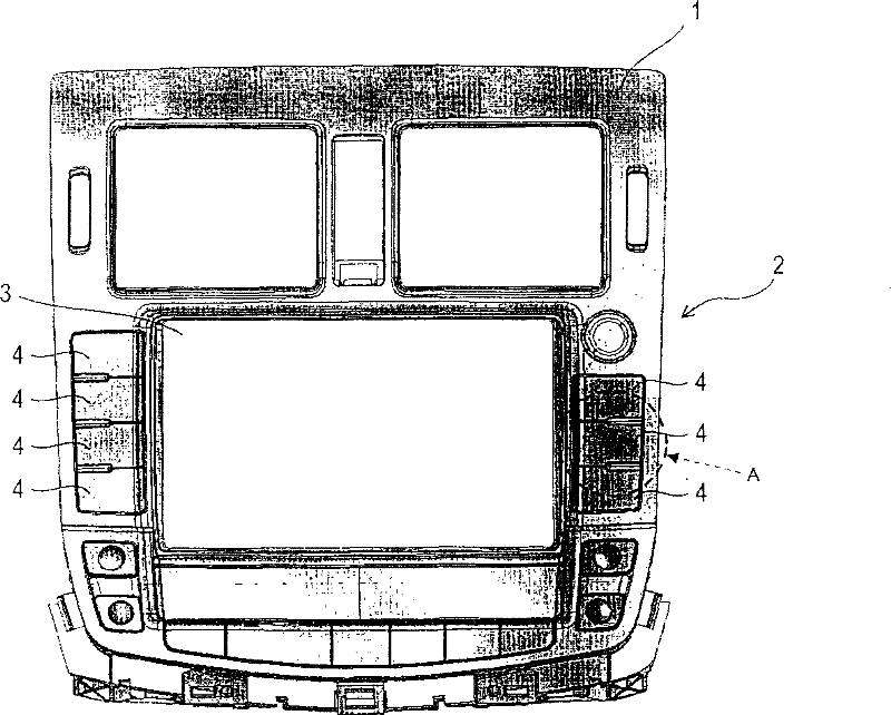
[0022] figure 1 It is an external view (front view) of the car navigation device 2 mounted on the dashboard 1 in the interior of the vehicle. The car navigation device 2 includes a plurality of switch devices 4 for performing various operations around a display screen 3 of a liquid crystal display.

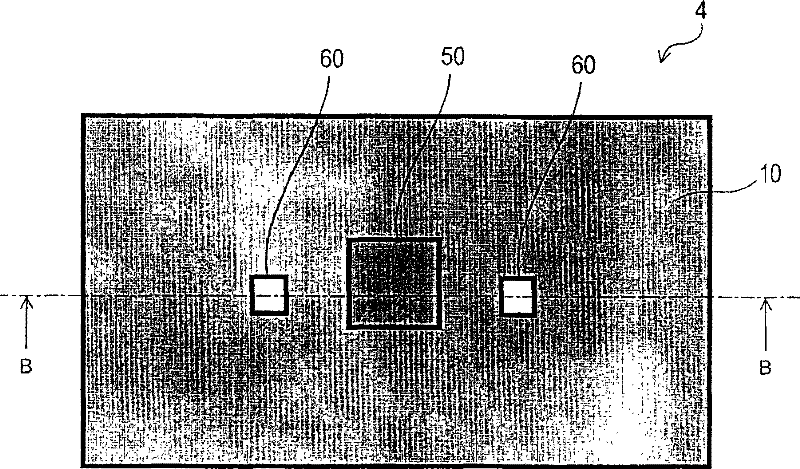
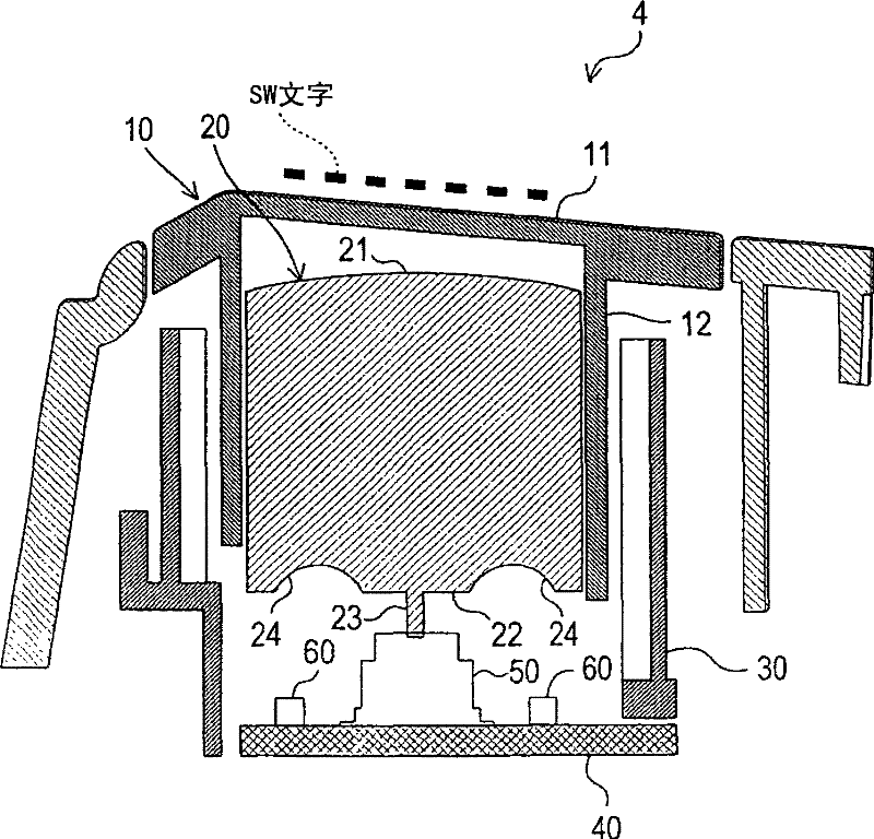
[0023] figure 2 yes figure 1 The enlarged view (schematic diagram) of the part indicated by arrow A in image 3 yes figure 2 B-B sectional view in . In addition, in figure 2 In the figure, in order to show the arrangement of the tact switch 50 and the LED 60 described later, they are shown in a see-through state.

[0024] The switch device 4 includes a button 10 , a lens 20 , a reflector 30 , a printed circuit board 40 , a tact switch 50 , and two LEDs 60 .

[0025] Button 10 is substantially box-shaped container shape ( image 3 The lower sid...


PUM


Abstract

The invention provides a switch (4) composed of an irradiation mechanism (60) having an operation body and irradiating light from inner side of the operation body to a translucent section, The operation has an operation face (11) formed with a translucent section and a push section (23) shifts for pushing a switch (50) by push force onto the operation face (11), the operation body is composed of an operation member (10) of the operation face (11) and a push member (20) of the push section (23), the push member (20) is formed with the translucent material. Therefore, the switch (4) may prevent retraction from generating on the operation face (11), restrain asymmetry of lightness and improve push operation feeling.

Description

technical field [0001] The invention relates to switching devices. Background technique [0002] Conventionally, a switch device for performing a push operation has been widely used (for example, refer to Patent Document 1). [0003] Generally, such a switch device is configured to include an operating body (button) supported in a displaceable state, and to displace the operating body to push an internal switch. Thus, the operation body is integrally formed with an operation surface to which a pressing force is applied from the outside, and a pusher for pressing an internal switch in response to displacement caused by the pressing force applied to the operation surface. parts (e.g. ribs). [0004] [Patent Document 1] Japanese Publication No. 60-106196 [0005] In a device including a plurality of such operating bodies, characters, illustrations, etc. can be displayed on the operating surface of each operating body, and the processing, movement, etc. performed by pushing a...

Claims


Application Information

Patent Timeline
Patent Type & Authority Patents(China)
IPC IPC(8): H01H13/02H01H9/18
Inventor 原一成
Owner DENSO CORP
Why Eureka
Try Eureka