Back light source device

A technology of backlight source and discharge tube, which is applied in the field of multi-lamp backlight source devices, can solve problems such as difficulty in improving brightness, and achieve the effects of realizing cost and suppressing uneven brightness.

Inactive Publication Date: 2008-11-12
SANKEN ELECTRIC CO LTD
View PDF4 Cites 0 Cited by
  • Summary
  • Abstract
  • Description
  • Claims
  • Application Information

AI Technical Summary

Problems solved by technology

[0004] The edge-light type is thin and has high brightness uniformity, but since the discharge tube is placed on the side and the light passing through the light guide plate is used, it has a side surface where it is difficult to improve brightness

Method used


Image

  • Back light source device
  • Back light source device
  • Back light source device

Examples


Embodiment 1

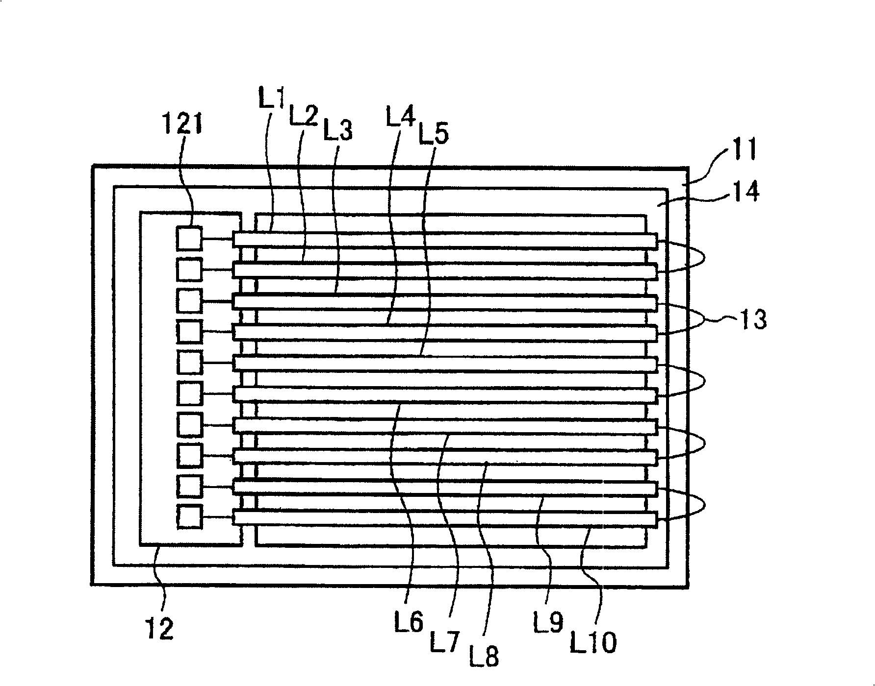
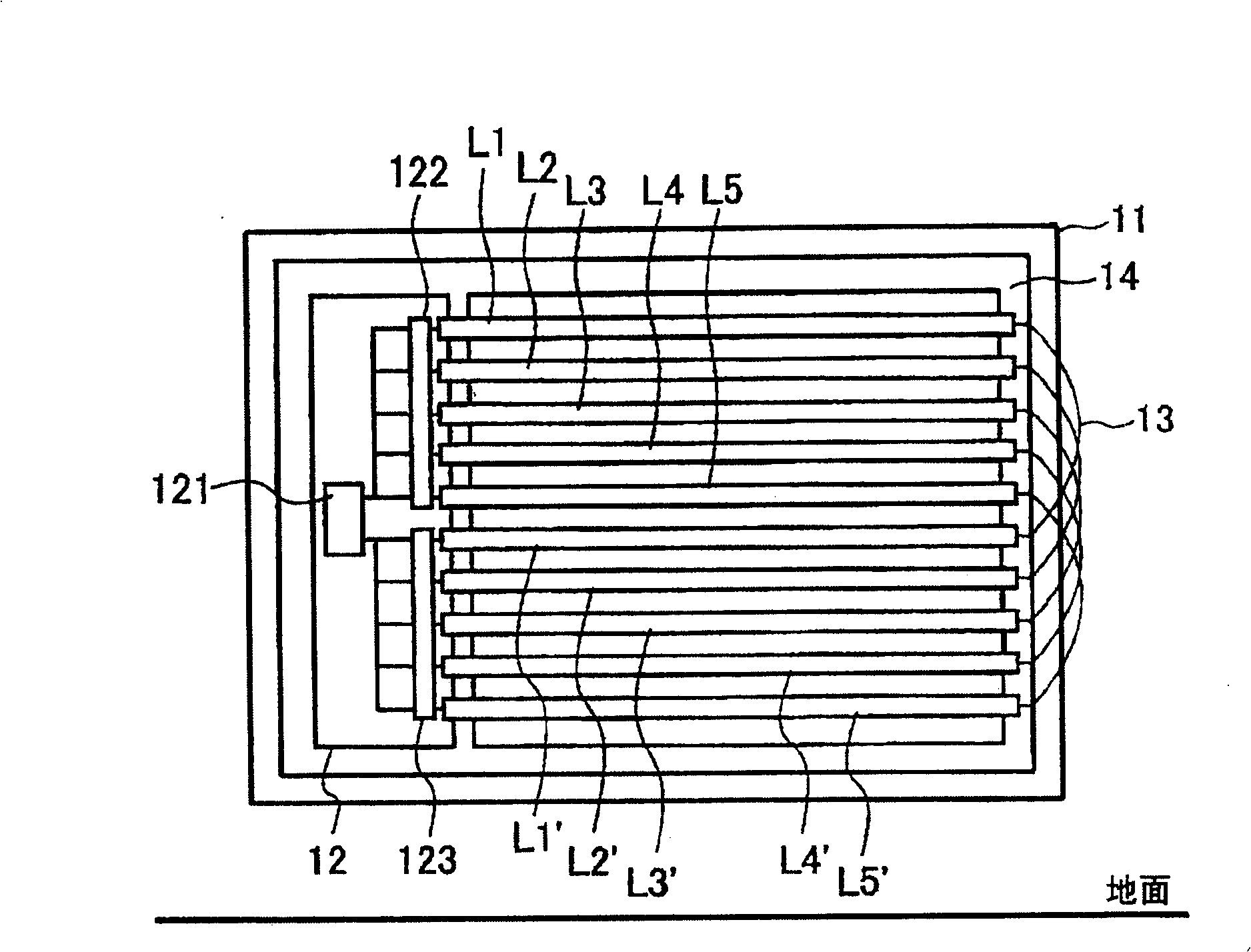
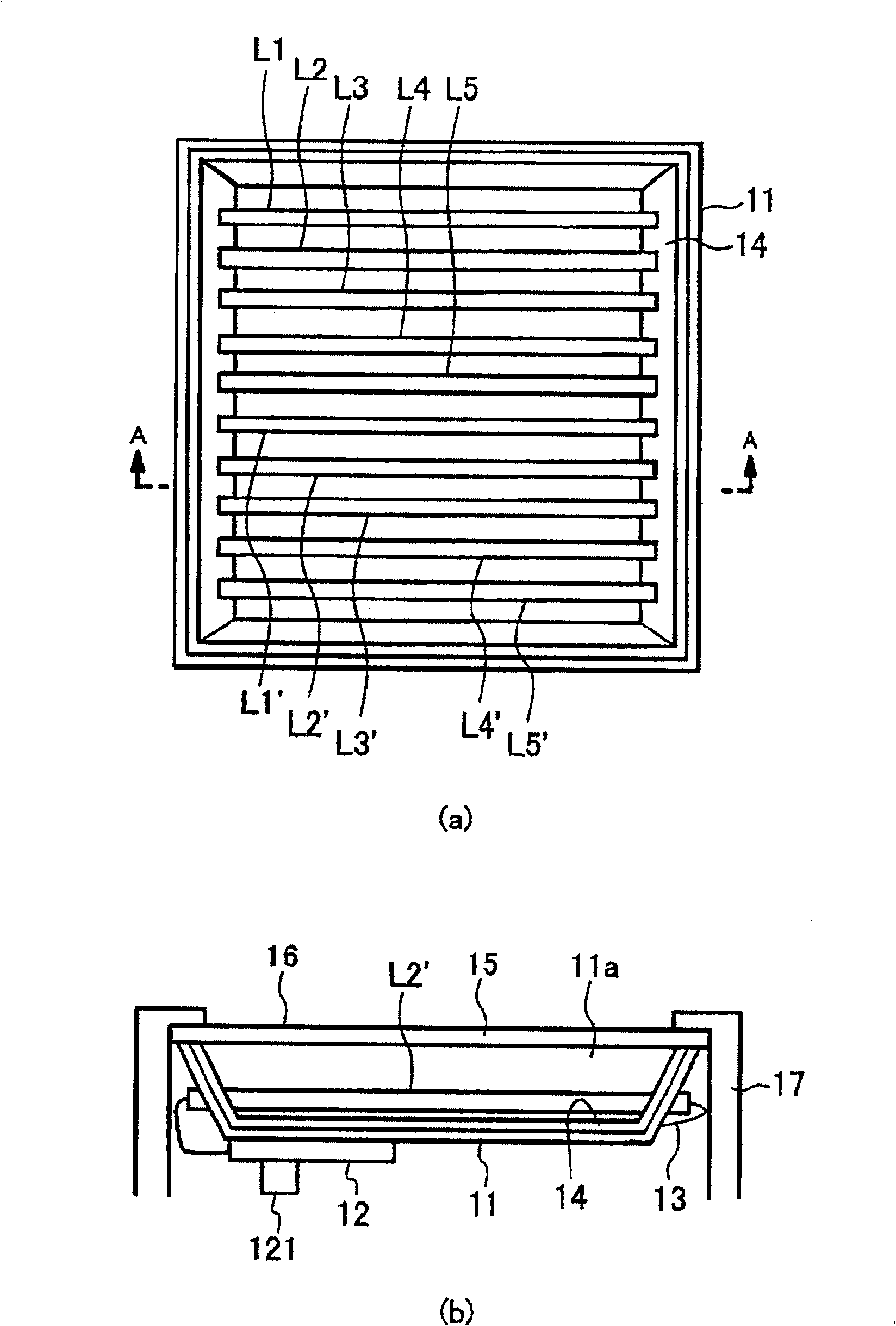
[0022] figure 2 It is a schematic diagram showing the relationship between the discharge tube and the inverter circuit in the backlight unit according to the first embodiment of the present invention. image 3 (a) is a plan view of the backlight unit according to Embodiment 1 of the present invention viewed from the display surface side. image 3 (b) is based on image 3 (a) Cross-sectional view of A-A after cutting. Such as Figure 2 ~ Figure 4 As shown, the backlight device according to Embodiment 1 of the present invention includes: a casing 11 , an even number of discharge tubes L1-L5 and L1'-L5', and an inverter circuit 12 . also, Figure 2 ~ Figure 3 This is an example when ten discharge tubes are used.

[0023] exist figure 2 Among them, the discharge tubes L1 to L5 and L1' to L5' are straight discharge tubes having a pair of electrodes, and are constituted by, for example, cold cathode tubes. The discharge tubes L1 to L5 and L1' to L5' are arranged in parallel...

Deformed example 1

[0040] Figure 5 It is a block diagram showing a modified example of the backlight unit according to Embodiment 1 of the present invention. Such as Figure 5 As shown, the backlight device of Embodiment 1 constitutes an inverter circuit 12a through two transformers. That is, in inverter circuit 12 a of Modification 1 of Embodiment 1, transformer 125 is provided in parallel with transformer 121 .

[0041] The electrode at one end of the discharge tube L1 arranged at the top of the first discharge tube group is connected to the electrode at one end of the discharge tube L1' arranged at the top of the second discharge tube group, and the analog U is formed by the discharge tube L1 and the discharge tube L1'. shaped tube. Similarly, the electrode arranged at one end of the second discharge tube L2 on the first discharge tube group is connected to the electrode arranged at one end of the second discharge tube L2' on the second discharge tube group. An electrode at one end of th...

Deformed example 2

[0045] Figure 6 It is a block diagram showing another modified example of the backlight unit according to Embodiment 1 of the present invention. Such as Figure 6 As shown, the backlight device of Modification 2 of Embodiment 1 consists of two transformers to form an inverter circuit 12b, and an even number (six or more) of discharge tubes are divided into four into a first discharge tube group composed of discharge tubes L1-Ln. , the second discharge tube group consisting of discharge tubes L1'-Ln', the third discharge tube group consisting of discharge tubes L1a-Lna, and the fourth discharge tube group consisting of discharge tubes L1a'-Lna'. In addition, in the inverter circuit 12 b of the modification 2 of the first embodiment, the transformer 125 is provided in parallel with the transformer 121 .

[0046] In addition, two of the first to fourth discharge tube groups are selected in order each time, the first group is composed of the first discharge tube group and the s...


PUM


Abstract

There is provided a back light source device comprising a housing 11 which is provided with an even number of discharge tubes (L1-L5), (L1'-L5'), each having a pair of electrodes. Said even number of discharge tubes is divided into a plurality of and even number of discharge tube groups, each having same number of discharge tubes. Two discharge tube groups are selected from said even number of discharge tube groups (L1-L5) and are regarded as a group every time. In each group, one end of a discharge tube selected from one discharge tube group selected from said two discharge tube groups is electronically connected to the other end of a discharge tube which is in the same row with said discharge tube and selected from the other discharge tube group (L1'-L5') selected from said two discharge tube groups.

Description

technical field [0001] The present invention relates to a backlight device of a liquid crystal display device used as various display devices, in particular to a backlight type multi-lamp backlight device. Background technique [0002] Since the liquid crystal display device cannot emit light by itself, an external light source such as a backlight device that irradiates light from the inner surface of the display surface is required. As an external light source, a discharge tube such as a cold cathode tube or a hot cathode tube is generally used. [0003] There are edge light type and back light type in the backlight device. The edge light type is to arrange discharge tubes on the side of the light guide plate, and use the light guide plate to emit light to the display surface. The backlight type is to arrange the discharge tube directly under the display surface, and arrange the reflector around it, and the direct light from the discharge tube and the reflected light refl...

Claims


Application Information

Patent Timeline
Patent Type & Authority Patents(China)
IPC IPC(8): G02F1/13357G02F1/1335H01J61/30H01J61/00
CPCG02F1/133604G02F1/133612H01J11/22Y02B20/00
Inventor 山下丰美松原正昭宇津野瑞木
Owner SANKEN ELECTRIC CO LTD
Why Eureka
Try Eureka