Optical diffusion plate for LED (Light Emitting Diode) lamp

An optical diffusion and diffusion plate technology, applied in the field of light diffusion plates, can solve the problems of inability to maximize the use of LED light rays, inability to recycle and reuse, and material pollution to the environment, so as to improve the utilization rate of light and solve the problem of partial lighting angle. Small, soft light effect

Active Publication Date: 2013-06-12
MEIZHOU JIANGNAN ELECTRICAL APPLIANCE
View PDF4 Cites 9 Cited by
  • Summary
  • Abstract
  • Description
  • Claims
  • Application Information

AI Technical Summary

Problems solved by technology

However, due to the inherent lighting characteristics of LED lights, there are problems such as glare and limitation of irradiation angles.
In order to solve these problems, it is basically solved by adding an optical diffusion cover, and the existing optical diffusion cover is basically at the expense of light transmission, using methods such as frosting, strip floating point, and large distance floating point. , can not maximize the use of LED lights to achieve the best lighting and energy-saving effects
Or, add opalescent agent, polarizing agent and other chemical raw materials to the material of the optical diffusion cover to increase the haze of the diffusion cover to achieve the goal. However, the materials produced in this way will pollute the environment and cannot be recycled and reused after use.

Method used


Image

  • Optical diffusion plate for LED (Light Emitting Diode) lamp
  • Optical diffusion plate for LED (Light Emitting Diode) lamp
  • Optical diffusion plate for LED (Light Emitting Diode) lamp

Examples


Embodiment 1

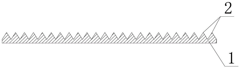
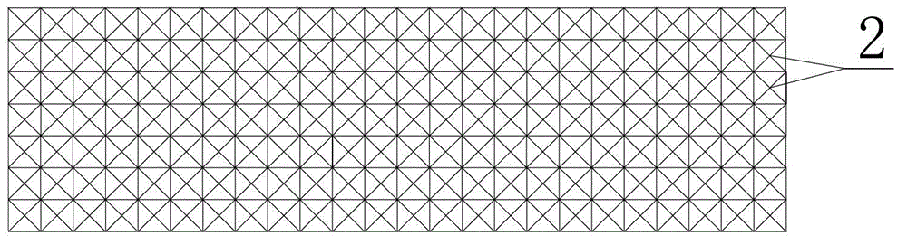
[0025] refer to figure 1 and figure 2 As shown, an optical diffuser plate for LED lights of the present invention includes a transparent first support plate 1, the first support plate 1 is a flat plate structure, and a number of first support plates are distributed on one side of the first support plate 1. Light refraction floating point 2, each of the first light refraction floating points 2 is a quadrangular pyramid, and each adjacent quadrangular pyramid is close together; the bottom surface side length of each quadrangular pyramid is 0.5 ~ 5mm, and the height is 0.4-4.3 mm, that is, the side triangles of each quadrangular pyramid are equilateral triangles. In this embodiment, the first support plate 1 and the first light refraction floating point 2 are integrally formed as an integral structure, which can be directly cast and formed, and the processing is very convenient. Because the first support plate 1 and the first light refraction floating point 2 No chemical raw m...

Embodiment 2

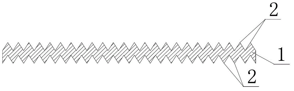
[0027] refer to image 3 As shown, an LED light optical diffuser plate of the present invention has basically the same structure as that of Embodiment 1, except that first light refraction floating points 2 are distributed on both sides of the first support plate 1, and the The first ray refraction floating point 2 located on both sides is misplaced. The diffusion plate with this structure has better diffusion effect, larger irradiation angle, better anti-glare effect and softer light.

Embodiment 3

[0029] refer to Figure 4 As shown, the structure of an optical diffuser cover for LED light of the present invention is basically the same as that of Embodiment 1, the difference is that a second support plate 3 is provided above the first support plate 1, and the first support plate 1 and the second support plate The two support plates 3 are connected by connecting rods 4; on the upper side of the second support plate 3, some second light refraction floating points 5 are distributed, and according to specific needs, they can also be distributed on the lower side of the second support plate 3, Each of the second light refraction floating points 5 is a quadrangular pyramid; the length of the bottom surface of each quadrangular pyramid is 0.5-5 mm, and the height is 0.4-4.3 mm; further, the first support plate 1 and the second support plate The distance between 3 is 0-5 mm. In this embodiment, the second support plate 3 is superimposed on the upper end of the first light refrac...


PUM


Abstract

The invention discloses an optical diffusion plate for an LED (Light Emitting Diode) lamp, belonging to the technical field of optical diffusion shells. The invention has the technical key point that the optical diffusion plate comprises a first transparent supporting plate, wherein a plurality of first light refraction floating points are distributed on at least one side face of the first supporting plate, and each first light refraction floating point is a rectangular pyramid; and the side length of the bottom face of each rectangular pyramid is 0.5-5 mm, and the height is 0.4-4.3 mm. The invention aims at providing an optical diffusion plate for an LED lamp with glare prevention, great irradiation angle, environmental protection and high light-admitting quality; and the optical diffusion plate is used for an LED lamp.

Description

technical field [0001] The present invention relates to a light diffusion plate, more specifically, to an LED light optical diffusion plate. Background technique [0002] LED lighting source, as a new type of energy-saving light source, has been vigorously promoted and used, representing the future development direction of lighting fixtures. However, due to the inherent lighting characteristics of LED lights, there are problems such as glare and limited irradiation angles. In order to solve these problems, it is basically solved by adding an optical diffusion cover, and the existing optical diffusion cover is basically at the expense of light transmission, using methods such as frosting, strip floating point, and large distance floating point. , unable to maximize the use of light from LED lights to achieve the best lighting and energy-saving effects. Alternatively, chemical raw materials such as opalescent agents and polarizers are added to the material of the optical dif...

Claims


Application Information

Patent Timeline
Patent Type & Authority Applications(China)
IPC IPC(8): F21V5/08F21Y101/02F21Y115/10
Inventor 陈志峰陈超
Owner MEIZHOU JIANGNAN ELECTRICAL APPLIANCE
Why Eureka
Try Eureka