
Power supply sampling circuit, power supply sampling method and fault indicator manufactured by same

A technology of sampling circuit and sampling module, which is applied in the direction of measuring current/voltage, instruments, measuring electricity, etc., can solve the problems of sampling distortion, increased material cost, and structural design requirements, etc., and achieves the effect of high reliability and low cost

Pending Publication Date: 2018-09-07
WILLFAR INFORMATION TECH CO LTD
View PDF0 Cites 5 Cited by
  • Summary
  • Abstract
  • Description
  • Claims
  • Application Information

AI Technical Summary

Problems solved by technology

However, the dual-CT sampling method not only increases the material cost, but also has requirements for the structural design, and the power-taking CT will affect the magnetic circuit of the sampling CT as the load changes, resulting in sampling distortion

Method used

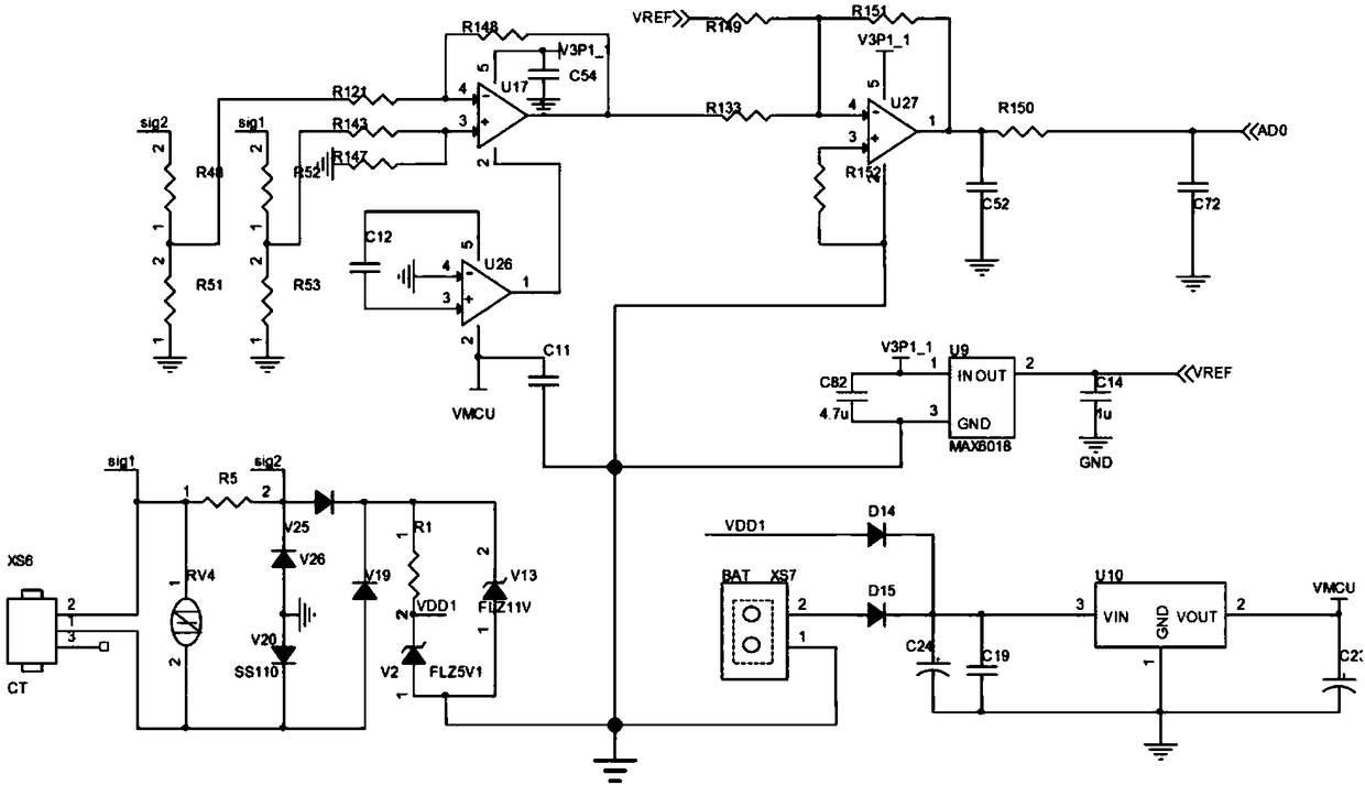

Image

  • Power supply sampling circuit, power supply sampling method and fault indicator manufactured by same
  • Power supply sampling circuit, power supply sampling method and fault indicator manufactured by same
  • Power supply sampling circuit, power supply sampling method and fault indicator manufactured by same

Examples


Embodiment Construction

[0026] Such as figure 1 Shown is a functional block diagram of the power supply sampling circuit of the present invention: the power supply sampling circuit provided by the present invention includes a current transformer, a rectification module, a protection module, a voltage stabilization module, a sampling module, a subtraction circuit module and a superposition circuit module; The input end of the current transformer is connected to the grid, the output end of the current transformer is connected in series with the sampling module, the rectification module, the protection module and the voltage stabilizing module in sequence, and the output end of the sampling module is also connected in series with the subtraction circuit module and the superposition circuit module; The output terminal of the transformer is divided into two signals after being sampled by the sampling module. The first signal outputs the power supply power through the rectification module, the protection mo...

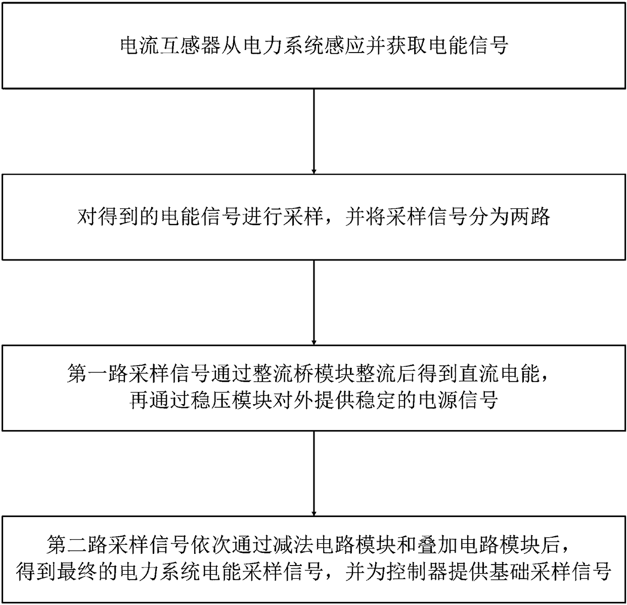

PUM


Abstract

The invention discloses a power supply sampling circuit which comprises a current transformer, a rectifier module, a voltage stabilizing module, a sampling module, a subtraction circuit module and a superimposed circuit module. The input end of the current transformer is connected with a power grid, the output end of the current transformer divides signals into two ways of signals through the sampling module, the first way of signals outputs electric energy for power supply through the rectifier module and the voltage stabilizing module, and the second way of signals outputs sampling data through the subtraction circuit module and the superimposed circuit module. The invention also discloses a power supply sampling method of the power supply sampling circuit. The power supply sampling method comprises the steps that the current transformer obtains signals; the signals are sampled and divided into two ways; the first way of signals provides power supply signals to the outside through the rectifier bridge module and the voltage stabilizing module the second way of signals are converted into final power system electric energy sampling signals through the subtraction circuit module andthe superimposed circuit module. The invention also discloses a fault indicator including the power supply sampling circuit and the power supply sampling method. The power supply sampling circuit only adopts one current transformer and is low in cost and high in reliability.

Description

technical field [0001] The invention specifically relates to a power supply sampling circuit, a power supply sampling method and a fault indicator made thereof. Background technique [0002] With the development of national economy and technology and the improvement of people's living standards, electric energy has become an indispensable secondary energy source in people's production and life, bringing endless convenience to people's production and life. [0003] In the power system, a large number of devices (such as fault indicators, etc.) need to take power and sample in the power grid at the same time: the purpose of taking power in the power grid is to obtain the power they need, so as to ensure the operation of the equipment itself. The purpose of sampling the power signal of the power grid is to obtain real-time data signals of power in the power grid, so as to monitor the power quality of the power grid. [0004] At present, the technical solution for equipment to ...

Claims


Application Information

Patent Timeline
Patent Type & Authority Applications(China)
IPC IPC(8): G01R31/02G01R19/00
CPCG01R19/00G01R31/50
Inventor 周到许健李君刘刚邓术邓勇夫
Owner WILLFAR INFORMATION TECH CO LTD
Learn More