Single-live-line double-control switch

A dual-control switch and single live wire technology, applied in electronic switches, electrical components, pulse technology, etc., can solve the problems of inability to realize dual-control functions, unfavorable popularization and application, and inconvenient installation, and achieve good use value, convenient use and Flexible, easy-to-install effects

Inactive Publication Date: 2014-04-23
温州坤美通信科技有限公司
View PDF3 Cites 0 Cited by
  • Summary
  • Abstract
  • Description
  • Claims
  • Application Information

AI Technical Summary

Problems solved by technology

[0003] The invention mainly solves the technical problems that the original ordinary electronic switch needs to be connected to the zero live wire, is not compatible with the traditional mechanical switch, and is inconvenient to install. It brings inconvenience to use and is not conducive to the technical problems of popularization and application; provides a single live wire double control switch, which adopts a single live wire power supply method, which can be consistent with the installation and wiring method of traditional mechanical switches, easy to install, and can be simply It replaces the traditional switch, and can realize the dual control function, which achieves the same function as the traditional mechanical dual control switch, meets people's needs for the use of dual control lamps, is easy to use, and can be well promoted and applied

Method used


Image

  • Single-live-line double-control switch
  • Single-live-line double-control switch
  • Single-live-line double-control switch

Examples


Embodiment 1

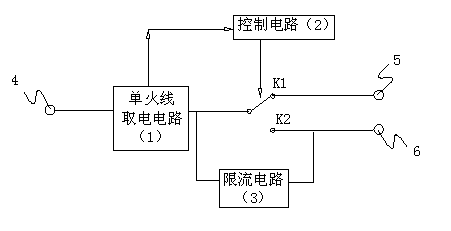
[0017] Embodiment 1: the single fire wire double control switch of this embodiment, such as figure 1 As shown, it includes a single live wire power-taking circuit 1, a control circuit 2, a relay J, a current limiting circuit 3, a first terminal 4, a second terminal 5 and a third terminal 6, and the first terminal 4 and the single live wire take The input terminals of the electric circuit 1 are connected, the first output terminal of the single live wire power-taking circuit 1 is connected to the second terminal 5 through a pair of normally closed contacts K1 of the relay J, and the other is connected through a pair of normally open contacts of the relay J Point K2 is connected to the third terminal 6, the current limiting circuit 3 is connected in parallel to the pair of normally open contacts K2, the second output terminal of the single live wire power-taking circuit 1 is connected to the working voltage input terminal of the control circuit 2, and the control circuit 2 The c...


PUM


Abstract

The invention relates to a single-live-line double-control switch, which comprises a single-live-line electricity taking circuit, a control circuit, a relay, a current limiting circuit, a first wiring terminal, a second wiring terminal and a third wiring terminal. The first wiring terminal is connected with the input end of the single-live-line electricity taking circuit, a branch of a first output end of the single-live-line electricity taking circuit is connected with the second wiring terminal through a pair of normally closed contacts of the relay, the other branch of the first output end of the single-live-line electricity taking circuit is connected with the third wiring terminal through a pair of normally open contact of the relay, the current limiting circuit is in parallel connection with the pair of normally open contacts, a second output end of the single-live-line electricity taking circuit is connected with a working voltage input end of the control circuit, and a control signal output end of the control circuit is connected with a driving end of the relay. The ingle-live-line double-control switch not only achieves single-live-line electricity taking, but also achieves double-control function, meets using requirements for double-control lamps of users, and is convenient and flexible to use and capable of being compatible with a traditional double-control mechanical switch. The single-live-line double-control switch and the traditional double-control mechanical switch are consistent in installation wiring mode, convenient to install and capable of being replaced simply.

Description

technical field [0001] The invention relates to a double control switch, in particular to an electronic single live wire double control switch. Background technique [0002] At present, ordinary electronic switches generally use zero live wires for power supply and need to be connected to two wires. It is incompatible with the installation structure of traditional mechanical switches that only need to be connected to one live wire, which brings inconvenience to installation, so it cannot be widely used. . At present, there are also electronic switches using a single live wire on the market, but they can only be connected to the load in a single-control mode, and the dual-control function cannot be realized, that is, the working mode of two switches controlling one lamp cannot be realized, which brings inconvenience to use and also Not conducive to the promotion of applications. Contents of the invention [0003] The invention mainly solves the technical problems that the...

Claims


Application Information

Patent Timeline
Patent Type & Authority Patents(China)
IPC IPC(8): H03K17/567
Inventor 蒋建强陈武
Owner 温州坤美通信科技有限公司
Why Eureka
Try Eureka