Key structure and its lifting mechanism

A lifting mechanism and button technology, applied in the direction of contact operating mechanism, electrical components, electric switches, etc., can solve the problems of poor combination accuracy of components, affecting the user's pressing feel, and poor actuation accuracy, etc., to achieve the best pressing feel and stability The effect of easy maintenance of degree, best combination accuracy and actuation accuracy

Active Publication Date: 2019-12-03
DARFON ELECTRONICS (SUZHOU) CO LTD +1
View PDF4 Cites 0 Cited by
  • Summary
  • Abstract
  • Description
  • Claims
  • Application Information

AI Technical Summary

Problems solved by technology

Generally speaking, compared with a connection structure that only allows rotation or sliding, a connection structure that allows both rotation and sliding needs to have a larger tolerance so that the components it connects (such as connecting the support to the keycap or base) can work smoothly. move, but this will make the assembly accuracy of the component poor and the actuation accuracy is also poor
For example, no matter whether the keycap is pressed or not, it is in a loose state, which will affect the user's pressing feel and is not conducive to the miniaturization of the key structure (for example, the keycap cannot provide stable movement due to excessive looseness).
Also, in some connection situations, the horizontal position of the keycap relative to the base will be different because the keycap is in an unpressed state or a pressed state, thus allowing the user to press the keycap. Feel the horizontal movement of the keycap, so that it will affect the user's pressing feel

Method used


Image

  • Key structure and its lifting mechanism
  • Key structure and its lifting mechanism
  • Key structure and its lifting mechanism

Examples


Embodiment Construction

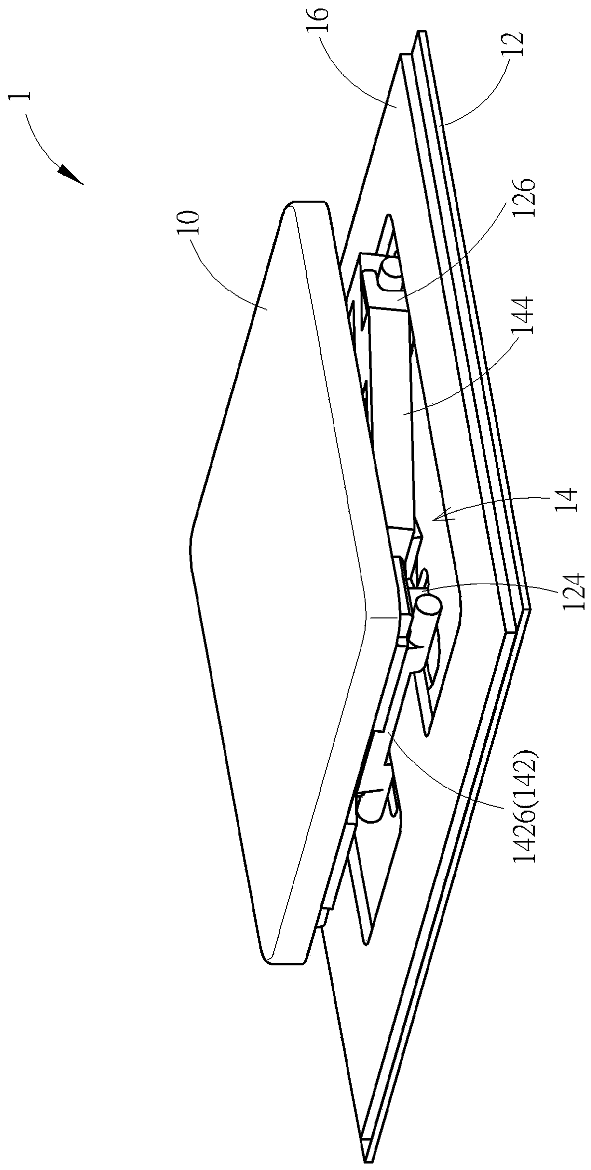
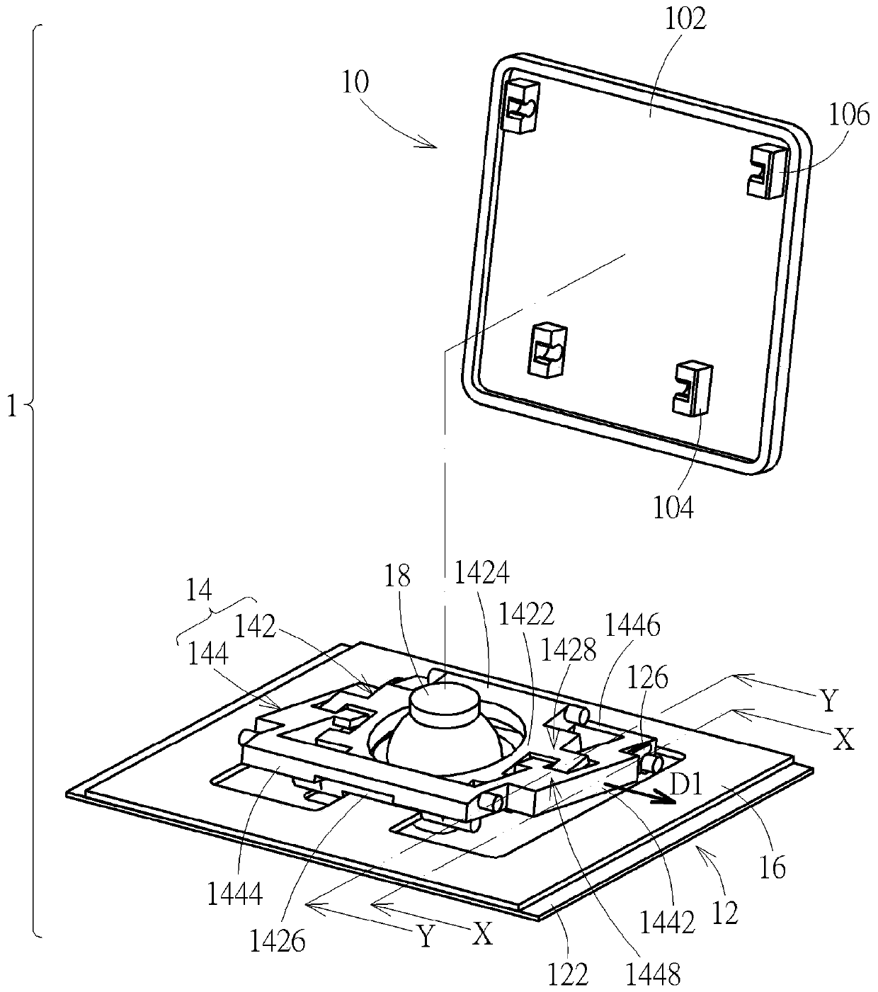
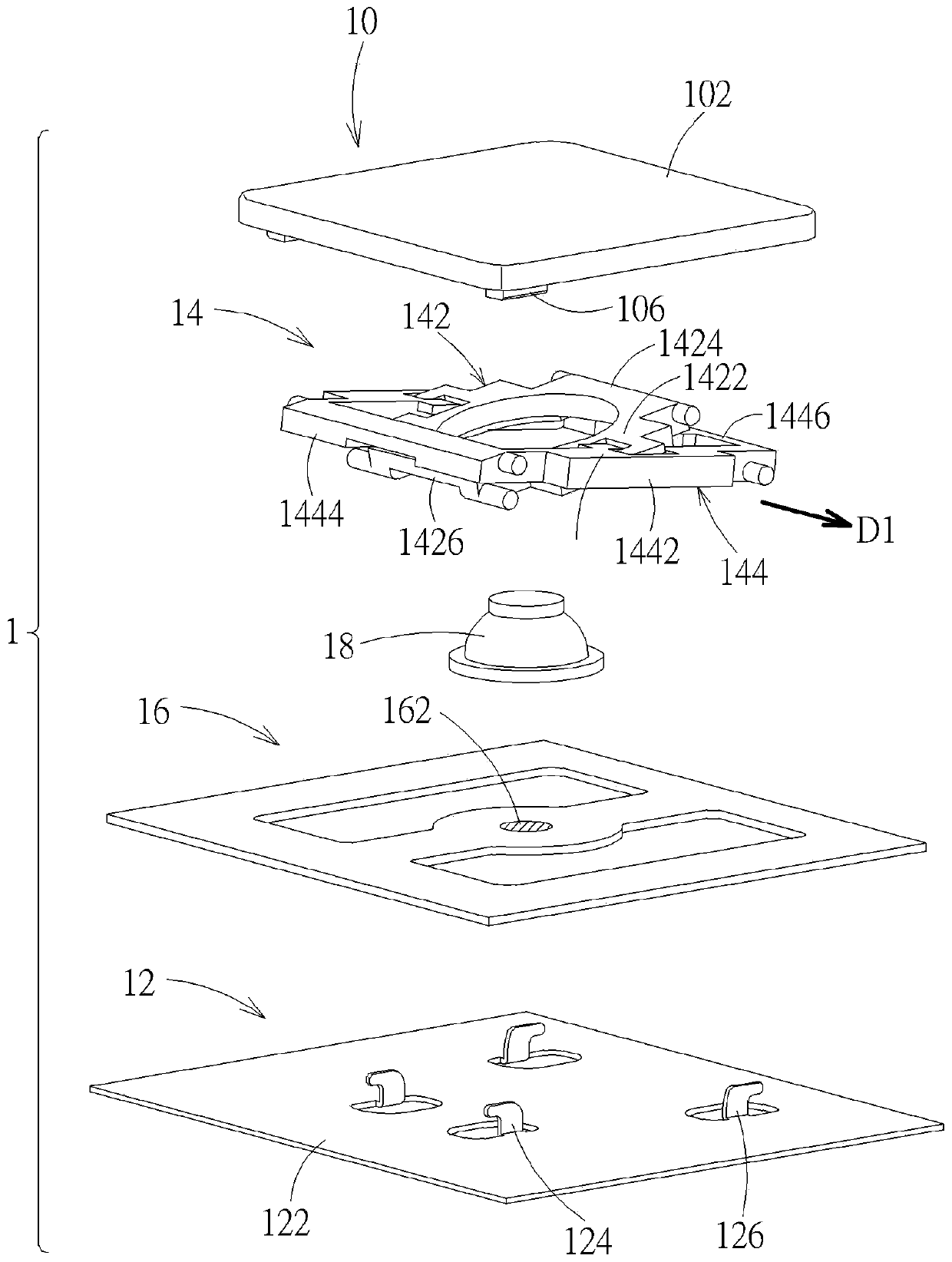
[0032] see Figure 1 to Figure 5 , figure 1 is a schematic diagram of a button structure according to an embodiment of the present invention, figure 2 for figure 1 Schematic diagram of the partial explosion of the middle button structure, image 3 for figure 1 Exploded diagram of the button structure in the middle, Figure 4 for image 3 Exploded diagram of the lifting mechanism of the middle button structure, Figure 5 for Figure 4 A schematic diagram of the second bracket of the middle lifting mechanism at another perspective. The key structure 1 according to an embodiment of the present invention includes a key cap 10 , a base 12 and a lifting mechanism 14 . The base 12 is disposed below the keycap 10 , and the lifting mechanism 14 is connected between the keycap 10 and the base 12 , so that the keycap 10 can move up and down relative to the base 12 via the lifting mechanism 14 . The button structure 1 also includes a thin film circuit board 16 and an elastic rou...


PUM


Abstract

The invention discloses a key structure. The key structure comprises a lifting mechanism connected between a key cap and a base. The lifting mechanism comprises a first support and a second support which are engaged with each other. The first support comprises a first groove and a first sliding part which are arranged adjacently along a first direction. The first groove is provided with a first curved bottom surface, and extends in the direction vertical to the first direction. The second support comprises a second sliding part and a second groove which are arranged adjacently along the firstdirection. The second groove is provided with a second curved bottom surface, and extends in the direction vertical to the first direction. The first sliding part is arranged on the second curved bottom surface in a sliding manner, and the second sliding part is arranged on the first curved bottom surface in the sliding manner. The first sliding part and the second sliding part simultaneously correspondingly slide on the second curved bottom surface and the first curved bottom surface, so that mutual rotation of the first support and the second support relative to the first direction is realized. The assembling accuracy of the key structure and the action stability of the lifting mechanism are easily maintained.

Description

technical field [0001] The invention relates to a key structure, in particular to a lifting mechanism of the key structure. Background technique [0002] At present, there are many mechanical key structures that use a pivoted support member as a lifting mechanism to support the keycap and provide a mechanism for the keycap to move up and down. For example, the scissors foot support is used as the lifting mechanism, which usually realizes the pivot connection with the cooperation of holes and shafts. When assembling the lifting mechanism, its supporting parts usually need to be deformed moderately so that the holes and shafts can be connected smoothly. When the key structure is miniaturized, the remaining deformation of the support member due to assembly will affect the assembly accuracy of the key structure, which also reduces the stability of the lifting mechanism, which is not conducive to the miniaturization of the key structure. In addition, the supports of the general...

Claims


Application Information

Patent Timeline
Patent Type & Authority Patents(China)
IPC IPC(8): H01H3/12H01H13/20H01H13/85
CPCH01H3/125H01H13/20H01H13/85
Inventor 赵令溪
Owner DARFON ELECTRONICS (SUZHOU) CO LTD
Why Eureka
Try Eureka