Check patentability & draft patents in minutes with Patsnap Eureka AI!

ATM (automated teller machine) and ATM operating method

A technology for ATM machines and banknotes, which is applied in the field of ATM machines and a banknote deposit process, which can solve problems such as poor banknote transfer, increased transportation failures, and banknote transportation failures, and achieve the effect of improving operating efficiency and performance stability

Pending Publication Date: 2018-09-14
SHANGHAI GOOAO ELECTRONIC TECHNOLOGY CORP
View PDF0 Cites 1 Cited by
  • Summary
  • Abstract
  • Description
  • Claims
  • Application Information

AI Technical Summary

Problems solved by technology

In the normal transaction process, when users use this kind of banknotes to deposit, it is very easy to cause various bad banknotes, and in severe cases, it will lead to banknote transportation failures
In particular, experiments have proved that if abnormal banknotes are deposited and then taken out, the probability of causing a transportation failure will increase exponentially

Method used


Image

  • ATM (automated teller machine) and ATM operating method
  • ATM (automated teller machine) and ATM operating method
  • ATM (automated teller machine) and ATM operating method

Examples


Embodiment 1

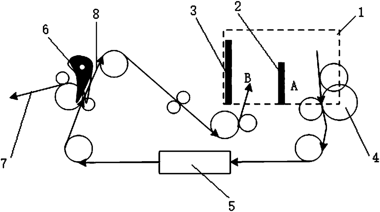
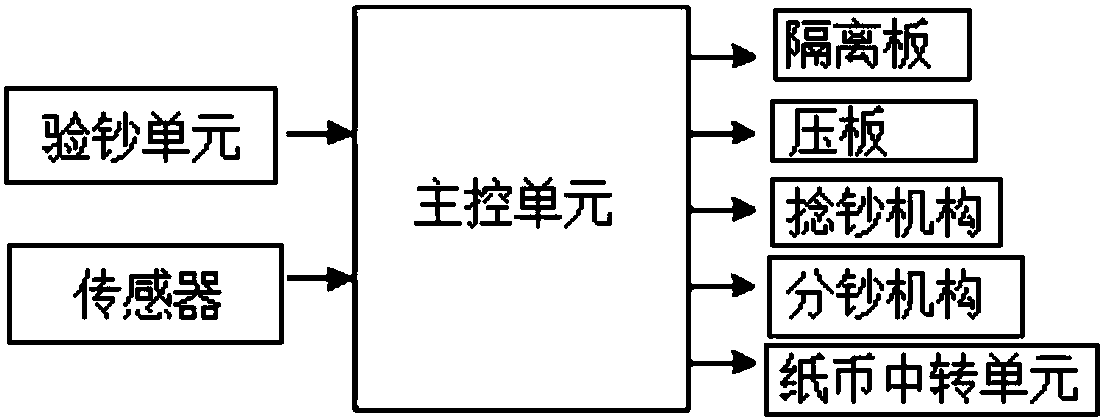
[0038] refer to figure 1 and figure 2 , the ATM machine of the present application includes a banknote deposit box, a main control unit, a banknote checking unit 5, a banknote detection sensor that is communicatively connected with the input terminal pin of the main control unit, and a banknote detection sensor that is communicatively connected with the output terminal pin of the main control unit. Twisting banknote mechanism 4, banknote separating mechanism 6; said twisting banknote mechanism 4 is positioned at the inner side of ATM machine banknote mouth 1, and banknote checking unit 5 is positioned at twisting banknote mechanism 4 downstream, and twisting banknote mechanism 4 outlets are aligned with banknote checking mechanism 5. The banknote opening, the banknote separating mechanism 6 is located at the downstream of the banknote checking mechanism 5, the banknote separating mechanism 6 is provided with a banknote returning unit and a banknote depositing unit, and the ba...

Embodiment 2

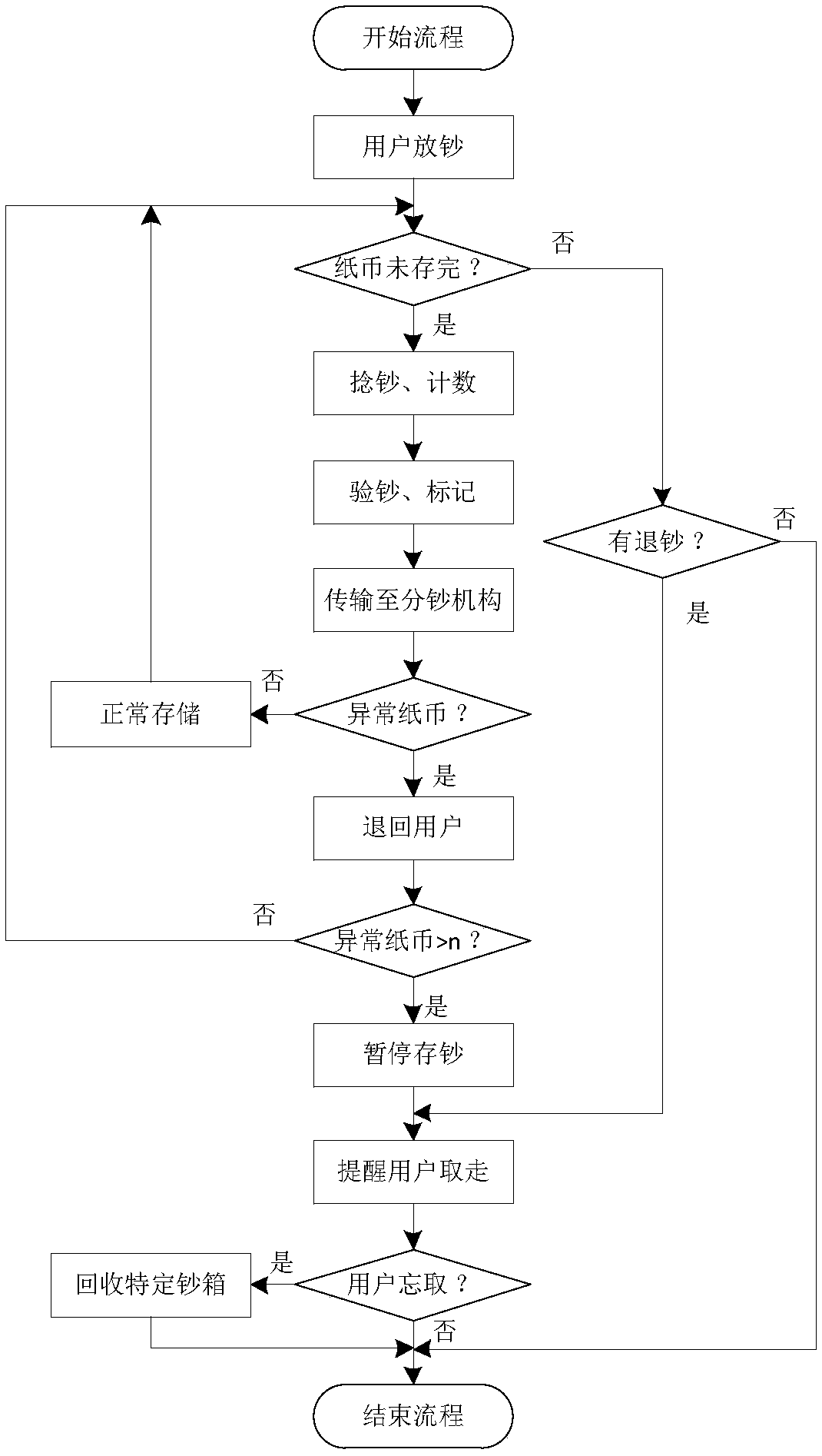
[0050] refer to figure 1 and image 3 , the ATM machine working method of the present application, or the storage process processing method includes:

[0051] When the deposit operation starts, the user puts banknotes into the banknote deposit port A at first. After the user confirms, the ATM closes the banknote deposit port baffle for banknote preprocessing, including a series of operations such as banknote detection, placement status sorting, push, voice prompts, etc., to ensure that the number and denomination of banknotes input by the user are normal.

[0052] After the banknotes are pretreated, the main control unit controls the banknote twisting mechanism 4 to start twisting banknotes, and the banknotes move from the banknote depositing place to the banknote checking unit 5 at a speed of several sheets per second. The banknote detection unit contains a micro-control module, which checks each banknote according to the algorithm programmed by the engineer in advance. Aft...


PUM


Abstract

The application provides an ATM (automated teller machine) and an ATM operating method. After a master control unit receives a cash depositing command, a cash entwisting mechanism is operated to convey cashes to a cash detection unit; when a cash detection sensor in the cash detection unit detects cash, the master control unit controls the cash detection unit to operate; during operating of the cash detection unit, the cash detection sensor counts the cashes and marks the abnormal ones; after cash detection, the cashes are conveyed to a cash dividing mechanism; the cash dividing mechanism judges whether the cashes are abnormal ones according to markings; if yes, a cash retreating unit retreats the cashes to a cash port; if not, a storage unit conveys the cashes to a storage box for storing. The abnormal cashes are judged and classified, and the abnormal cashes are circulated in the machine fewer times; from the entry source of the ATM, the abnormal cashes are avoided being circulated inside the machine; therefore, cash inclination and jamming chances due to the abnormal cashes are effectively decreased.

Description

technical field [0001] The present application relates to an ATM machine and a working method thereof, in particular to an ATM machine and a cash deposit flow processing method. Background technique [0002] ATM (Automated Teller Machines), also known as automatic teller machines, as a high-precision electromechanical integration device, directly faces the public, which facilitates the daily cash transaction activities of the public and also reduces the workload of banks. At present, it has been widely popularized in China. . [0003] At present, the ATM models that have been applied in the market include cash machines and all-in-one deposit and withdrawal machines. The services provided mainly include cash deposit and withdrawal, transfer, balance inquiry, password change and other functions. According to the operating principle of the ATM movement, the all-in-one cash deposit and withdrawal machine is much more complicated: on the one hand, in order to prevent users from ...

Claims


Application Information

Patent Timeline
Patent Type & Authority Applications(China)
IPC IPC(8): G07F19/00
CPCG07F19/202
Inventor 邵亚强王乐福
Owner SHANGHAI GOOAO ELECTRONIC TECHNOLOGY CORP
Features
  • R&D
  • Intellectual Property
  • Life Sciences
  • Materials
  • Tech Scout
  • Unparalleled Data Quality
  • Higher Quality Content
  • 60% Fewer Hallucinations
Learn More