Seed cotton residual film removing machine

A technology of removing machine and residual film, which can be used in the separation of plant fibers from seeds, mechanical treatment, textiles and paper making, etc. It can solve the problems of damaged seed cotton fibers and fragile residual film.

Active Publication Date: 2018-09-18
DONGGUAN DINGMAO SPRAY PURIFICATION SYST
11 Cites 0 Cited by

AI-Extracted Technical Summary

Problems solved by technology

[0004] The purpose of the present invention is to provide a seed cotton residual film removal machine that has a good effect of removing residual film to impro...

Method used

In order to ensure the uniformity of the air supply of a single air supply assembly, and then the residual film can be fully exposed on the surface of the seed cotton to facilitate the removal of the residual film with the air flow, in the present embodiment, preferably, a plurality of exhaust holes with Arranged in array, adopting this arrangement, the process is simple, and it is also beneficial to reduce the production cost.
In this embodiment, the air storage cavity is provided with a gasket, such as the lower waist plate 4.1 of the first air supply assembly, the lower waist plate 4.1 of the second air supply assembly, the lower waist plate 4.2 of the third air supply assembly, the fourth air supply assembly Gasket 2, gasket 2.1, gasket 2.2, Gasket 2.3, Gasket 2.4, Gasket 2.5, Gasket 2.6; the air supply duct is provided with a gasket, for example, the bottom plate 8 of the first air supply duct is provided with a gasket 7. It should be noted that the number of gaskets is not limited to the above, and they are arranged at all connections between the air storage cavity and the air supply duct to ensure a good sealing effect.
Preferably, for the convenience of the installation of the air storage chamber, the upper waist plate of the air storage chamber is horizontally arranged, so that the opening direction of the vent hole is inclined relative to the upper waist plate, so that the gas discharged through the vent hole The airflow flows obliquely upwards. Simultaneously, the box body left side wall 23 that will be provided with the cotton inlet 22 and the box body right side wall 33 that is provided with the cotton outlet 20 are also obliquely arranged relative to the board where the upper waist board is located, and the box body left side wall 23 and the box body The inclination direction of the right side wall 33 is consistent with the inclination direction of the exhaust hole, so as to facilitate the airflow in the uniform box interior 35 and prevent local eddy currents from being generated.
Preferably, the dust cage dust net is connected with the coupling 42 by the dust net end connector 41, and the casing is provided with a bearing 40, so as to effectively support the rotating dust basket dust net effect.
Specifically, the air st...

Abstract

The invention relates to the technical field of cotton processing, in particular to a seed cotton residual film removing machine. The seed cotton residual film removing machine comprises an air floating part, a removing part arranged above the air floating part and a box body used for connecting the air floating part with the removing part; the box body is provided with a cotton inlet and a cottonoutlet; the air floating part comprises a plurality of air supply assemblies arranged in parallel, each air supply assembly comprises an air supply pipeline and an air storage cavity communicated with the air supply pipeline and provided with an exhaust end, the exhaust end of each air storage cavity comprises a plurality of exhaust holes, the exhaust holes are obliquely formed so that air flow exhausted from the exhaust holes can flow obliquely upwards, and the air speeds of the air flow introduced into every two adjacent air supply pipelines are different; the removing part comprises a plurality of removing assemblies which are located in the box body and sequentially arrayed in the direction from the cotton inlet to the cotton outlet. Residual film is fully exposed on the surface layerof seed cotton through the air flow flowing obliquely upwards and removed by the removing part accordingly, seed cotton fibers are not damaged through the mode of removing the residual film, and thequality of ginned cotton is high.

Application Domain

Vegetable fibre separation from seeds

Technology Topic

AirflowWind speed +2

Image

  • Seed cotton residual film removing machine
  • Seed cotton residual film removing machine
  • Seed cotton residual film removing machine

Examples

  • Experimental program(1)

Example Embodiment

[0027] In order to make the objectives, technical solutions, and advantages of the embodiments of the present invention clearer, the technical solutions in the embodiments of the present invention will be described clearly and completely in conjunction with the accompanying drawings in the embodiments of the present invention. Obviously, the described embodiments It is a part of the embodiments of the present invention, but not all the embodiments. Based on the embodiments of the present invention, all other embodiments obtained by those of ordinary skill in the art without creative work shall fall within the protection scope of the present invention.
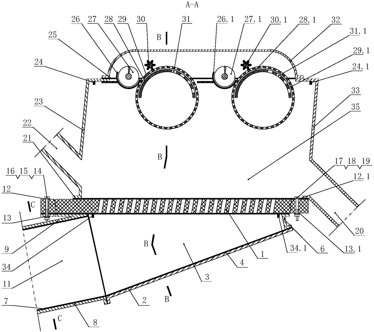
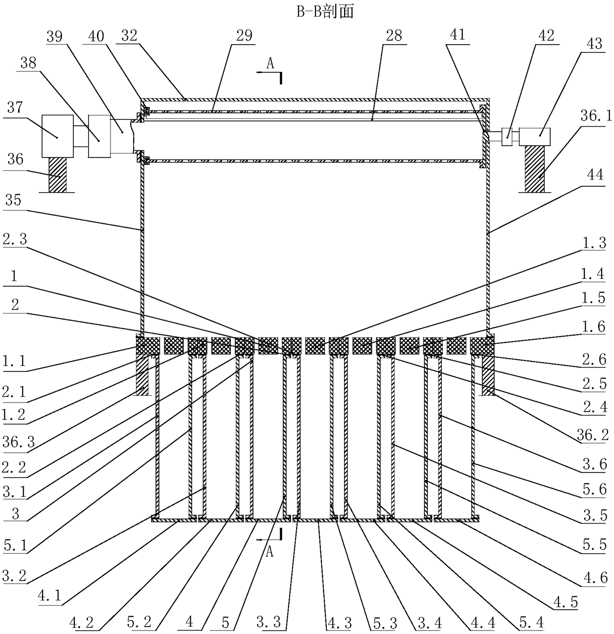
[0028] It should be noted that in the following embodiments, figure 1 The A-A section direction is defined as the longitudinal section direction of the gas storage cavity; figure 2 The end plate in the direction shown on the left in the middle is defined as the left end plate, correspondingly, it will be located figure 2 The end plate in the direction shown on the right is defined as the right end plate.
[0029] Such as Figure 1 to Figure 7 As shown, the embodiment of the present invention provides a seed cotton residue film removal machine, which includes an air flotation component, a cleaning component arranged above the air flotation component, and a box for connecting the air flotation component and the cleaning component. The box is provided with an inlet Cotton port 22 and cotton outlet 20; the air flotation component includes a plurality of air supply components arranged in parallel, each air supply component includes an air supply pipe and an air storage cavity connected with the air supply pipe and having an exhaust end, and the air storage cavity The exhaust end includes a plurality of exhaust holes, the exhaust holes are arranged obliquely so that the airflow discharged through the exhaust holes flows obliquely upward, and the wind speed of the airflow into two adjacent air supply ducts is different; the cleaning component includes multiple The cleaning components are located in the box, and a plurality of cleaning components are arranged in sequence from the cotton inlet 22 to the cotton outlet 20.
[0030] The cleaning machine provided by the present application includes an air flotation component, a cleaning component, and a box body connecting the air flotation component and the cleaning component. The box body includes the left side wall 23, the top cover 32, and the right side wall of the box that are connected in sequence 33. There are cotton inlet 22 and cotton outlet 20 on the box body to figure 1 The direction shown in the figure is taken as an example. The cotton inlet 22 is provided on the left side wall 23 of the box body, and the cotton outlet 20 is provided on the right side wall 33 of the box body; the air flotation component is used to provide oblique upward flow for the seed cotton in the box body. Airflow, so that the residual film can be fully exposed to the surface of the seed cotton, where the oblique upward airflow can not only provide upward support for the seed cotton, but also provide the seed cotton with the direction from the cotton inlet 22 to the cotton outlet 20. Thrust; the cleaning component provides a negative pressure airflow to absorb and remove the residual film exposed on the surface of the seed cotton.
[0031] In this way, this application uses airflow to remove the residual film in the seed cotton without damaging the seed cotton fiber; in particular, the present invention removes the residual film in the seed cotton to avoid the subsequent impact of the mechanical parts on the residual film during the ginning process. This method of removing residual film from seed cotton can ensure the quality of lint processing. In addition, the cleaning machine provided in this application has a reasonable design, a good removal effect of residual film, and strong practicability, which is beneficial to standardized production and promotion.
[0032] Preferably, in this embodiment, the air storage cavity in the air supply assembly has a closed chamber structure with an air intake end and an exhaust end, wherein the air intake end of the air storage cavity is in communication with the air supply duct, and the exhaust end is A plurality of exhaust holes are provided, and the plurality of exhaust holes are communicated with the inside 35 of the box, so that the airflow discharged through the exhaust holes can enter the inside 35 of the box.
[0033] According to the preference of the above technical solution, the longitudinal section of the air storage cavity is in the shape of an isosceles trapezoid, the exhaust holes are provided on the upper lumbar plate of the air reservoir with the longitudinal section of the isosceles trapezoid shape, and the lower lumbar plate is made of sheet material; The small end of the lower lumbar plate is connected by a connecting plate, and the two sides of the upper lumbar plate are respectively connected to both sides of the lower lumbar plate through an end plate; the large end of the upper lumbar plate and the lower lumbar plate and the two end plates constitute the air inlet end of the air storage chamber, The air inlet end is connected with the air supply duct.
[0034] In order to ensure that the air flow with better tearing of the seed cotton can be provided, the air storage cavity preferably adopts an isosceles chamber structure, such as an isosceles triangle or an isosceles trapezoid. Among them, the upper lumbar plate is provided with exhaust holes as the exhaust end, and the lower lumbar plate is the bottom plate of the air storage cavity, which is sealed.
[0035] Further preferably, in this embodiment, the air storage cavity adopts an isosceles trapezoidal chamber structure, including an upper lumbar plate, a lower lumbar plate and two end plates for connecting the upper lumbar plate and the lower lumbar plate. The small end is connected by a connecting plate, and the large ends of the upper lumbar plate and the lower lumbar plate and two end plates constitute an air inlet end communicating with the air supply duct. Among them, the two end plates include the left end plate and the right end plate. The upper lumbar plate is provided with multiple exhaust holes. The upper lumbar plate, the left end plate, the lower lumbar plate and the right end plate are connected in sequence, and the lower lumbar plate, left end plate, right end plate and connecting plate are all connected. It is made of plates to form a chamber structure with a sealed chamber.
[0036] Among them, the plate is preferably a galvanized steel plate, and the upper waist plate is preferably a non-metallic material. In this way, the strength of the air storage cavity can be ensured and the weight of the device can be reduced, and the process is simple and inexpensive.
[0037] In this embodiment, for the convenience of presentation, it is described as an example with 7 air supply components:
[0038] The first air supply component includes an upper lumbar plate 1, a lower lumbar plate 4, a left end plate 3, and a right end plate 5. The small ends of the upper lumbar plate 1 and the lower lumbar plate 4 are connected by a connecting plate 6; the upper lumbar plate 1 and the large end of the lower lumbar plate 4 are formed The air inlet end is connected with the first air supply duct. Correspondingly, the first air supply duct includes a bottom plate 8, a top plate 9, a right side plate 10, and a left side plate 11. The bottom plate 8, the left side plate 11, the top plate 9 and the right side plate 10 are connected in sequence to form a front and rear inlet and outlet. The cavity structure of the air outlet, wherein the air outlet of the first air supply duct is in communication with the large end of the air storage cavity.
[0039] The second air supply component includes the upper lumbar plate 1.1, the lower lumbar plate 4.1, the left end plate 3.1, and the right end plate 5.1; the third air supply assembly includes the upper lumbar plate 1.2, the lower lumbar plate 4.2, the left end plate 3.2, and the right end plate 5.2; fourth air supply Components, including upper lumbar plate 1.3, lower lumbar plate 4.3, left end plate 3.3, right end plate 5.3; fifth air supply assembly, including upper lumbar plate 1.4, lower lumbar plate 4.4, left end plate 3.4, right end plate 5.4; sixth air supply assembly, including upper Lumbar plate 1.5, lower lumbar plate 4.5, left end plate 3.5, right end plate 5.5; the seventh air supply component, including upper lumbar plate 1.6, lower lumbar plate 4.6, left end plate 3.6, and right end plate 5.6.
[0040] According to a preference of the above technical solution, the upper waist plate includes a plate body and a plurality of exhaust holes penetrating the plate body.
[0041] In this embodiment, the upper waist plate is a sheet structure with a thickness, and a plurality of exhaust holes penetrating the thickness of the sheet can be provided on the sheet as required. Among them, the exhaust holes only need to be able to provide air flow for removing residual film. That is, the specific shape and quantity can be specifically set according to actual needs.
[0042] According to the preference of the above technical solution, a plurality of air supply components are arranged along a direction perpendicular to the cotton inlet 22 pointing to the cotton outlet 20, the upper waist plate is arranged horizontally, and the opening direction of the exhaust hole is arranged obliquely with the surface of the upper waist plate The box body includes two side walls respectively provided with a cotton inlet 22 and a cotton outlet 20. The two side walls are inclined with the surface of the upper waist plate, and the inclined direction is consistent with the inclined direction of the exhaust hole.
[0043] Preferably, in order to facilitate the installation of the air storage cavity, the upper lumbar plate of the air storage cavity is arranged horizontally. In this way, the opening direction of the exhaust hole is arranged obliquely with respect to the surface of the upper lumbar plate, so that the air flow discharged through the exhaust hole is inclined upward flow. At the same time, the left side wall 23 of the box body with the cotton inlet 22 and the right side wall 33 of the box body with the cotton outlet 20 are also inclined to the surface where the upper waist plate is located, and the left side wall 23 of the box body and the box body The inclination direction of the right side wall 33 is consistent with the inclination direction of the exhaust hole, so as to facilitate uniform airflow in the box interior 35 and prevent local vortex flow.
[0044] In addition to the above, the upper waist plate can also be arranged non-horizontally. Correspondingly, the opening direction of the vent hole and the setting direction of the left side wall 23 and the right side wall 33 of the box body can be in line with the upper waist plate. The inclined arrangement can also be arranged perpendicular to the surface of the upper waist plate, as long as the airflow discharged through the exhaust hole flows obliquely upwards and the setting direction of the two side walls is consistent with the opening direction of the exhaust hole. Among them, the opening arrangement of the vent hole and the arrangement of the upper lumbar plate can be reasonably selected and set according to the actual implementation conditions.
[0045] According to the preference of the above technical solution, the range of the angle between the opening direction of the vent hole and the surface of the upper waist plate is ≥70° and <90°.
[0046] More preferably, when the upper lumbar plate is set horizontally, the opening direction of the vent hole is arranged obliquely to the surface of the upper lumbar plate, and the preferred angle is ≥70° and <90°. In this way, the seed cotton can be under the action of airflow for a long time It is suspended in the air to remove residual film, and at the same time, it can move toward the direction of the cotton outlet 20 under the action of airflow, so as to perform uninterrupted residual film removal operations on large quantities of seed cotton.
[0047] In order to ensure the uniformity of the air supply of a single air supply component, and then fully expose the residual film on the surface of the seed cotton to facilitate the removal of the residual film by air flow, in this embodiment, preferably, multiple exhaust holes are arranged in an array. With this arrangement, the process is simple, and it also helps reduce production costs.
[0048] According to the preference of the above technical solution, it further includes a frame for installing air floating components and cleaning components, each cleaning component includes a dust cage, a brush, auger and a baffle; the dust cage includes a fixed box The upper dust cage stator part and the dust cage dust net connected to the motor 43 through the coupling 42. The two ends of the baffle are respectively fixed on the walls of the front and rear sides of the box. The ends of the screw and the brush are respectively passed through the bearing The components are fixed on the frame; among them, the dust cage and the dust net of the dust cage are tangent to the brush and rotate in opposite directions. The linear velocity direction of the two at the tangent point is the same and diagonally downward. The auger is located diagonally below the brush and The rotation direction of the brush is the same, and the baffle is located under the auger.
[0049] The cleaning machine provided in the present application also includes a frame, wherein the air flotation component and the cleaning component are both installed on the frame. In this embodiment, the upper lumbar plate in the air floating part is fixed on the frame 36.2 and the frame 36.3; the motor 43 and the fan 37 in the cleaning part are supported on the frame 36.1 and the frame 36, respectively.
[0050] Specifically, the cleaning assembly includes a dust cage, a brush, an auger and a baffle, and the two ends of the auger and the brush are respectively fixed on the frame through a bearing assembly (not shown in the figure). When the seed cotton enters the inside 35 of the box through the cotton inlet 22, the oblique upward airflow from the exhaust hole lifts the seed cotton and tears the seed cotton thinly so that the residual film is exposed on the surface of the seed cotton. In this way, it passes through the coupling 42 and The dust cage dust net connected to the motor 43 rotates under the drive of the motor 43, and the negative pressure inside absorbs the residual film, and the brush is tangent to the dust cage dust net and rotates opposite to each other to brush the residual film adsorbed on the surface of the dust cage dust net. The auger is located obliquely below the brush and rotates in the same direction as the brush to transport the residual film under the brush to the outside of the box; the baffle is located under the auger to prevent the residual film from being brushed off. It falls on the upper waist plate of the air floating component. On the other hand, the two ends of the baffle are respectively fixed on the front and back walls of the box, and the baffle is set close to the dust cage, so that the upper part of the box is isolated from the outside air to ensure the box. The airflow inside 35 is not affected by outside air.
[0051] Preferably, the dust-cage dust net is connected to the coupling 42 through the end connecting member 41 of the dust-net, and a support 40 is provided on the box body to effectively support the rotating dust-cage dust net.
[0052] According to the preference of the above technical solution, the dust cage stator part includes a non-porous arc part and a hole arc part connected with the non-porous arc part. A mounting hole is opened on the wall of the box body of the fixed dust cage stator part, and the fan 37 It communicates with the dust cage through connecting components and mounting holes.
[0053] Preferably, the stator part of the dust cage is set as a non-porous arc part and a hole arc part. The non-porous arc part is used to block the airflow on the dust cage dust net, and the hole arc part makes a small amount of airflow on the dust cage dust net. By adopting the above-mentioned structure of the dust cage stator part, the negative pressure formed in the dust cage dust net can effectively absorb the residual film on the surface of the seed cotton. At the same time, the residual film can be smoothly brushed down with a brush and then removed by the screw auger. More preferably, the openings on the perforated arc part are larger than the openings on the dust net of the dust cage.
[0054] In this embodiment, for the convenience of presentation, two clearing components are provided as an example for description:
[0055] The first cleaning component includes a dust cage, a brush 30, a screwdriver 27 and a baffle 26; wherein the dust cage includes a dust cage dust net 29 and a dust cage stator part, and the dust cage stator part includes a non-porous arc part 28 and The non-porous arc portion 31 connected to the non-porous arc portion 28;
[0056] The second cleaning component includes the dust cage, the brush 30.1, the screw 27.1 and the baffle 26.1; among them, the dust cage includes the dust cage dust net 29.1 and the dust cage stator part, and the dust cage stator part includes the non-porous arc part 28.1 and The non-porous arc part 28.1 is connected to the non-porous arc part 31.1.
[0057] According to the preference of the above technical solution, the upper lumbar plates of two adjacently arranged air supply components are arranged side by side, and the two adjacently arranged upper lumbar plates are fixedly connected by a connecting piece.
[0058] In order to connect a plurality of air supply components into a whole device, in this embodiment, the upper waist plates of two adjacent air supply components are fixedly connected. Specifically, the connecting piece includes an upper connecting plate, a lower connecting plate and a bolt assembly. During installation, the two upper connecting plates are respectively placed on both ends of the end faces of two adjacent upper waist plates, and the two lower connecting plates are respectively Place two adjacent upper lumbar plates at both ends of the lower end surface, drill holes in the upper connecting plate, lower connecting plate and two upper lumbar plates, and finally pass through the upper connecting plate, upper lumbar plate and lower connecting plate by bolts in turn After the holes are fixed, they are fastened by nuts or nuts and washers to realize the fixed connection of two adjacently arranged air supply components.
[0059] In this embodiment, taking the fixed connection of two adjacently arranged first air supply components and third air supply components as an example, the upper connecting plate 12 is placed on the upper end surface of the upper lumbar plate 1, the left end of the upper lumbar plate 1.2, and the lower connection The plate 13 is placed on the lower end surface of the left end of the upper lumbar plate 1, the upper lumbar plate 1.2, and the upper connecting plate 12, the lower connecting plate 13, the upper lumbar plate 1 and the upper lumbar plate 1.2 are drilled, and finally the upper connecting plate is passed through the first bolt group 14 12. After the holes of the upper lumbar plate 1, the upper lumbar plate 1.2 and the lower connecting plate 13, they are then fastened by the first nut set 15 and the first washer set 16;
[0060] The upper connecting plate 12.1 is placed on the upper end surface of the upper lumbar plate 1, the upper lumbar plate 1.2, the lower connecting plate 13.1 is placed on the upper lumbar plate 1, the upper lumbar plate 1.2, and the upper connecting plate 12.1, the lower connecting plate 13.1, and the upper lumbar plate 1. Drill holes on the upper lumbar plate 1.2, and finally pass through the holes of the upper connecting plate 12.1, upper lumbar plate 1, upper lumbar plate 1.2 and lower connecting plate 13.1 through the second bolt group 17, and then pass through the second nut group 18 and the second pad The piece group 19 is fastened.
[0061] Further preferably, in order to prevent the air flow from leaking during the flow process, sealing gaskets are provided at all connections between the air storage cavity and the air supply duct. Among them, the gasket can be made of rubber material, which is inexpensive and has a good sealing effect. Of course, asbestos gaskets or cork gaskets can also be used as gaskets, and a reasonable gasket material type can be selected according to actual implementation conditions.
[0062] In this embodiment, the air storage cavity is provided with sealing gaskets, such as the lower waist plate 4 of the first air supply assembly, the lower waist plate 4.1 of the second air supply assembly, the lower waist plate 4.2 of the third air supply assembly, and the fourth air supply assembly The lower lumbar plate 4.3 of the fifth air supply assembly, the lower lumbar plate 4.4 of the fifth air supply assembly, the lower lumbar plate 4.5 of the sixth air supply assembly, and the lower lumbar plate 4.6 of the seventh air supply assembly are respectively provided with a gasket 2, a gasket 2.1, a gasket 2.2, and a seal. Gasket 2.3, gasket 2.4, gasket 2.5, gasket 2.6; the air supply duct is provided with a gasket, such as a gasket 7 on the bottom plate 8 of the first air duct. It should be noted that the number of sealing gaskets is not limited to the above, and is provided at all connections between the air storage cavity and the air supply pipe to ensure a good sealing effect.
[0063] According to the preference of the above technical solution, further, it further includes a first pressure sensor group and a second pressure sensor group. Both the first pressure sensor group and the second pressure sensor group include a plurality of pressure sensors, and the pressure sensors of the first pressure sensor group The pressure sensor of the second pressure sensor group is arranged in the box.
[0064] Further, in order to ensure the smooth, orderly, reliable and safe operation of the cleaning machine, the cleaning machine provided in the present application is further provided with a first pressure sensor group and a second pressure sensor group. Wherein, the first pressure sensor group and the second pressure sensor group both include multiple pressure sensors. For example, in this embodiment, the pressure sensor 34 and the pressure sensor 34.1 of the first pressure sensor group are respectively arranged on both sides under the upper lumbar plate. The pressure sensor 24 and the pressure sensor 24.1 of the second pressure sensor group are respectively arranged on both sides of the upper part of the box, so that the airflow pressure value in the air storage cavity and the box can be detected in real time during the removal of the residual film of the seed cotton to ensure safety operation.
[0065] According to the preference of the above-mentioned technical solution, each air supply assembly further includes a blower, and two adjacent blowers provide airflows with different pressures and speeds, so that the airflow velocity discharged from the exhaust holes of the multiple air supply assemblies is Wavy.
[0066] In this way, airflows of different pressures and speeds can be introduced into the air supply ducts of adjacent air supply components, so that the airflow speeds discharged from the exhaust holes are different, and the airflow speeds out of the air storage cavity are wave-shaped, such as Figure 7 For v1, v2 and v3 with different flow rates, if the pressure and flow rate of the air flow in the device are reasonably controlled, the seed cotton can be torn into a sufficiently thin wave-shaped thin layer, and the dust cage in the cleaning module can absorb all above the seed cotton thin layer. Residual film, and use a brush and auger to remove the residual film, which is beneficial to improve the residual film removal effect.
[0067] In addition to the above, the seed cotton residual film removal machine provided by this application also includes the following technical features:
[0068] Specifically, the air storage cavity adopts an isosceles trapezoidal cavity structure. Correspondingly, its intake end composed of an upper lumbar plate, a left end plate, a lower lumbar plate, and a right end plate is in the shape of a rectangular mouth to ensure that the air supply duct and the storage For the connection effect of the air cavity, the cross section of the air supply pipe is also designed to be rectangular, and the rectangular air supply port of the air supply pipe and the air inlet end of the air storage cavity are detachably connected by a flange, which has a good connection strength.
[0069] To sum up, the present invention provides a seed cotton residual film removal machine, which includes an air flotation component, a cleaning component arranged above the air flotation component, and a box for connecting the air flotation component and the cleaning component, and the box is provided with an inlet Cotton port and cotton outlet; the air float component includes a plurality of air supply components arranged in parallel, each air supply component includes an air supply pipe and an air storage cavity connected with the air supply pipe and having an exhaust end, and the exhaust of the air storage cavity The air end includes a plurality of vent holes, the vent holes are arranged obliquely so that the airflow discharged through the vent holes flows obliquely upward, and the airflow speeds into two adjacent air supply ducts are different; the cleaning component includes a plurality of located in the box The cleaning components in the body are arranged in sequence from the cotton inlet to the cotton outlet. The oblique upward airflow at different flow rates tears the seed cotton thin and fully exposes the residual film on the surface of the seed cotton, and then the residual film is adsorbed and cleaned by the removal component; in particular, the present invention removes the residual film from the seed cotton to avoid subsequent rolling The impact of mechanical parts on the residual film during the flowering process causes it to be broken into a large number of small fragments that cannot be removed. This method of removing residual film from seed cotton can ensure the quality of lint processing. In addition, the cleaning machine provided in this application has reasonable design, good removal effect of residual film, strong practicability, and is conducive to standardized production and promotion.
[0070] Finally, it should be noted that the above embodiments are only used to illustrate the technical solutions of the present invention, not to limit it; although the present invention has been described in detail with reference to the foregoing embodiments, those of ordinary skill in the art should understand that: The technical solutions recorded in the foregoing embodiments are modified, or some of the technical features are equivalently replaced; these modifications or replacements do not cause the essence of the corresponding technical solutions to deviate from the spirit and scope of the technical solutions of the embodiments of the present invention.

PUM

no PUM

Description & Claims & Application Information

We can also present the details of the Description, Claims and Application information to help users get a comprehensive understanding of the technical details of the patent, such as background art, summary of invention, brief description of drawings, description of embodiments, and other original content. On the other hand, users can also determine the specific scope of protection of the technology through the list of claims; as well as understand the changes in the life cycle of the technology with the presentation of the patent timeline. Login to view more.
Why Eureka
Try Eureka