Phase iteration minimization based Fourier ptychographic microscopy image reconstruction method

A technology of Fourier stacking and image reconstruction, which is applied in the directions of image and image conversion, image data processing, instruments, etc., to achieve the effect of good reconstructed intensity image quality

Active Publication Date: 2018-09-18
WUHAN UNIV
View PDF8 Cites 14 Cited by
  • Summary
  • Abstract
  • Description
  • Claims
  • Application Information

AI Technical Summary

Problems solved by technology

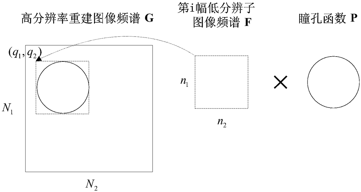
[0005] The present invention proposes a Fourier stack imaging image reconstruction method based on phase iterative minimization, which belongs to the Fourier stack imaging method and solves the problem of how to obtain a series of low-resolution images in Fourier stack imaging. The problem of efficiently reconstructing high-resolution images from images can be applied to various Fourier stack imaging systems

Method used


Image

  • Phase iteration minimization based Fourier ptychographic microscopy image reconstruction method
  • Phase iteration minimization based Fourier ptychographic microscopy image reconstruction method
  • Phase iteration minimization based Fourier ptychographic microscopy image reconstruction method

Examples


Embodiment 1

[0085] 1. The simulation data adopts the attached Figure 5 As the original high-resolution intensity image X (input is an intensity image, generate a low-resolution amplitude sub-image according to step S1), appended Image 6 As the original high-resolution phase image Y, the resolution is 512×512. Based on attached Figure 5 And attached Image 6 Build a simulation input high-resolution image Z=X(cosY+i×sinY);

[0086] 2. Based on the principle of Fourier stack imaging, a series of low-resolution sub-images are generated by Z, the resolution is 64×64, a total of 225 sub-images, and the high-resolution image spectrum corresponding to the spectrum of adjacent low-resolution sub-images The positions overlap in a certain area, and the number of iterations is 100;

[0087] 3. The simulated pupil function is as attached Figure 7 As shown, its size is 64×64. Take the center (assuming its space coordinates are (m i ,m j )) is a dot, and the radius r=26 is the radius to draw...

Embodiment 2

[0092] 1. Adopt the same simulation input high-resolution image Z=X(cosY+i×sinY) as in embodiment 1;

[0093] 2. Based on the principle of Fourier stack imaging, a series of low-resolution sub-images are generated by Z, the resolution is 128×128, a total of 36 sub-images, and the high-resolution image spectrum corresponding to the spectrum of adjacent low-resolution sub-images The positions overlap in a certain area, and the number of iterations is 100;

[0094] 3. The simulated pupil function is as attached Figure 10 As shown, its size is 128×128. Take the center (assuming its space coordinates are (m i ,m j )) is a dot, and the radius r=51 is the radius to draw a circle. The calculation process for the value P(x,y) at the pupil function coordinates (x,y) is as follows:

[0095] if Then P(x,y)=1; otherwise, P(x,y)=0.

[0096] 4. The reconstructed high-resolution intensity image X' and high-resolution phase image Y' (both resolutions are 512×512) are as attached Fig...


PUM


Abstract

The invention belongs to the technical field of a Fourier ptychographic microscopy, and especially relates to a phase iteration minimization based Fourier laminate imaging image reconstruction method.The method includes the following steps: S1, generating a series of amplitude sub-images corresponding to low-resolution sub images; S2, obtaining reconstruction algorithm parameters, the parametersincluding the positions of frequency spectrums generated by each low-resolution sub image in high-resolution reconstruction spectrums, pupil functions, etc., and building the relation between the low-resolution sub images and high-resolution reconstruction images; S3, taking phase recovery as one of optimization targets, generating a target function for image reconstruction target optimization, performing solving through iterative minimization, and obtaining frequency spectrums of a high-resolution reconstruction image; and S4, performing Fourier inverse transformation on the frequency spectrums of the high-resolution reconstruction image, using the models of results as the images after high-resolution reconstruction. The method performs the high-resolution image reconstruction by using the low-resolution sub images with the same numbers, and therefore, better reconstruction intensity image quality can be achieved.

Description

technical field [0001] The invention belongs to the technical field of Fourier stack imaging, in particular to a Fourier stack imaging image reconstruction method based on phase iteration minimization. Background technique [0002] Since the birth of the first microscope to the present, optical microscopic imaging technology has developed rapidly, and people's requirements for image quality are also getting higher and higher. People hope to obtain both high-resolution images and a large field of view. However, in ordinary optical imaging equipment, the field of view and magnification cannot be combined. A large field of view will inevitably lead to insufficient magnification. Although the larger shape of the object can be observed, the finer parts of the object cannot be seen clearly; on the contrary, a high magnification will inevitably lead to a too small field of view, which is not conducive to observing the shape of the object. In theory, increasing the numerical apertu...

Claims


Application Information

Patent Timeline
Patent Type & Authority Applications(China)
IPC IPC(8): G06T3/40
CPCG06T3/4076
Inventor 田昕李松
Owner WUHAN UNIV
Why Eureka
Try Eureka