
Four-directional rotation shaft structure based on modular assembly

A rotating shaft and modular technology, applied in the direction of pivot, shaft and bearing, pivot connection, etc., can solve the problem of not being able to ensure the modularity of the rotating shaft structure at the same time, it is difficult to meet the modular product shape, and the modular product shape is single and other issues, to achieve the effect of rich shape design, ingenious structural design, and high modularity

Pending Publication Date: 2018-09-21
HUNAN YUEGANG MOOKRAY IND CO LTD
View PDF6 Cites 0 Cited by
  • Summary
  • Abstract
  • Description
  • Claims
  • Application Information

AI Technical Summary

Problems solved by technology

The same module can be spliced ​​into ever-changing product shapes. However, in the splicing process, due to the different shapes, when it is necessary to splice modules for corners or other special-shaped structures, it is necessary to develop a corresponding rotating shaft structure as a module. However, in the process of modeling transformation of modular products, in order to improve the diversity and richness of modular products in the process of modeling transformation, the rotation direction required by each node is often not A single direction, and the currently developed rotating shaft structure is difficult to achieve rotation adjustment in different directions. Most of the rotating shaft structures can only be rotated and adjusted in one or two dimensions for the modeling of modular products. This leads to a single shape of the modular product. If it is necessary to realize the steering adjustment of the rotating shaft structure in a multi-dimensional space, it is impossible to ensure the modularity of the rotating shaft structure at the same time, and it is difficult to meet the increasingly rich modular products.

Method used


Image

  • Four-directional rotation shaft structure based on modular assembly
  • Four-directional rotation shaft structure based on modular assembly
  • Four-directional rotation shaft structure based on modular assembly

Examples


Embodiment Construction

[0024] The present invention will be further elaborated below in conjunction with the accompanying drawings and specific embodiments.

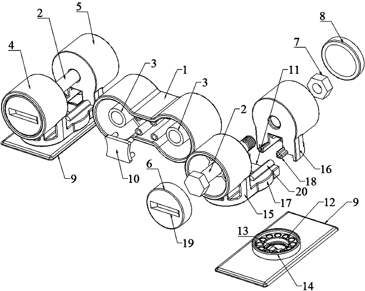
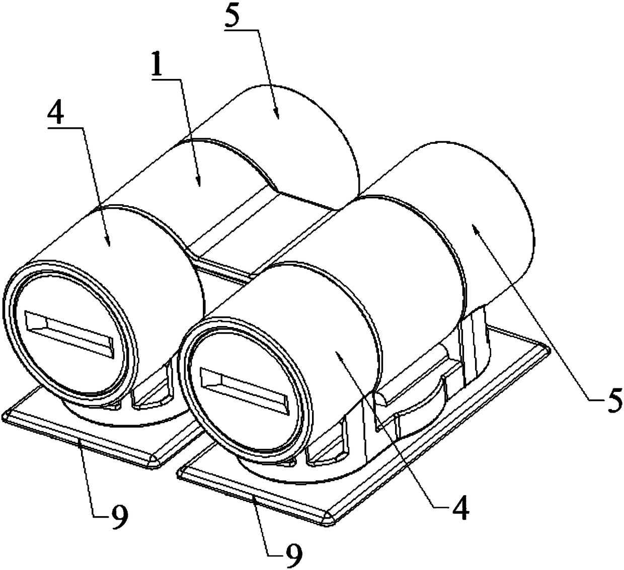
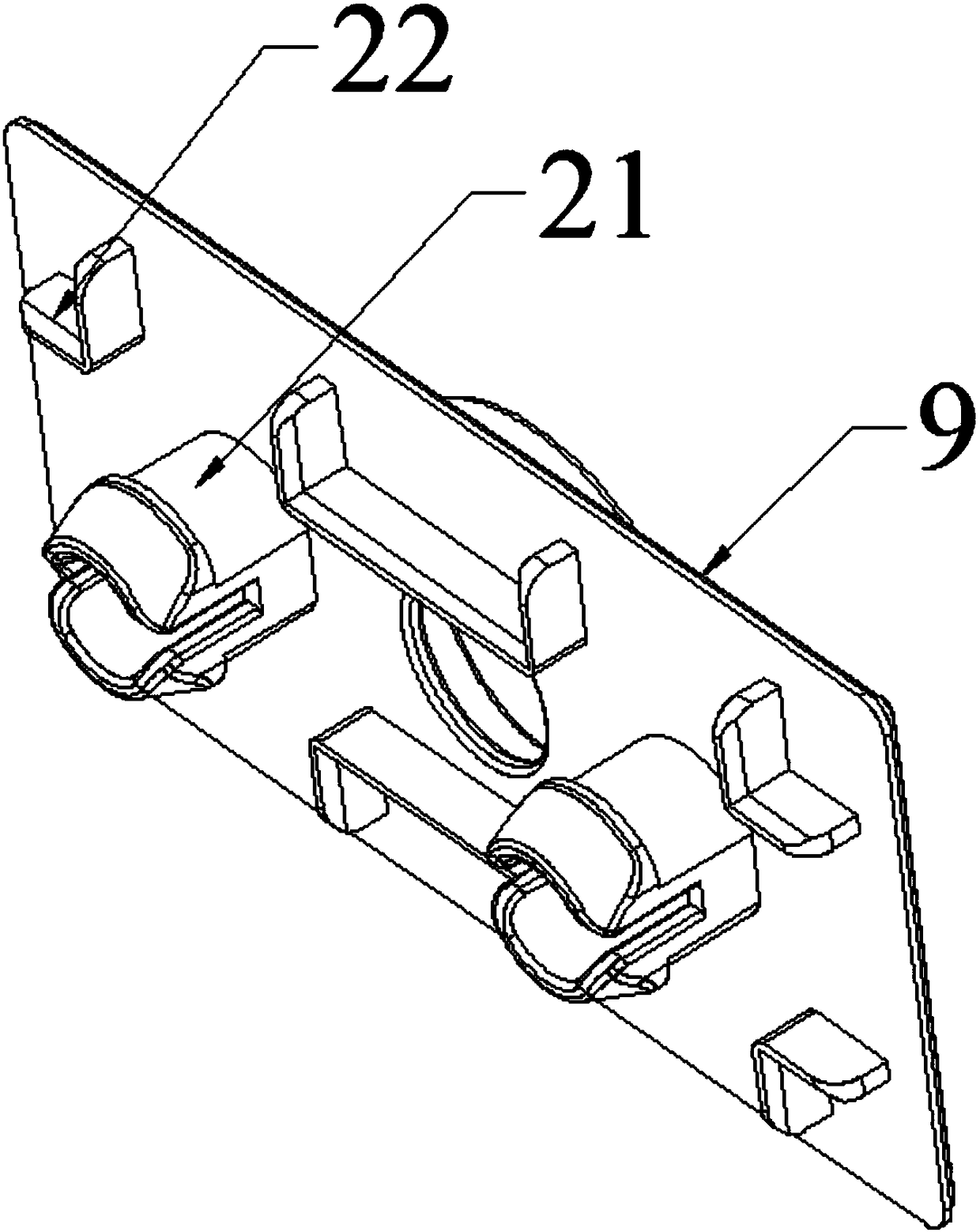
[0025] Such as Figure 1-Figure 4 As shown, the present invention provides a four-way rotating shaft structure based on modular assembly, including a co-directional shaft 1, the co-directional shaft 1 is a hollow shell with one side open and the cross-section of the hollow shell is 8 font, the codirectional shaft 1 is composed of a middle shell and an arc shell connected to both ends of the middle shell, and the inside of the codirectional shaft 1 is a connected cavity, and the centers of the two ends of the codirectional shaft 1 are A bolt shank 2 is movably socketed (the center of the circle is the center of the arc shell), and the bolt shank 2 is located in the direction of the axis of the circle center at the end of the coaxial shaft 1 (the axis of the circle center is the axis of the arc shell), Preferably, a rotating sleeve 3 is provide...


PUM


Abstract

The invention discloses a four-directional rotation shaft structure based on modular assembly, belonging to the technical field of modularized lamps. The four-directional rotation shaft structure comprises a homodromous shaft, which is a hollow shell with an 8-like cross section, wherein circle centers at two ends of the homodromous shaft both movably sleeve one bolt bar; supporting assemblies, wherein one sides of the supporting assemblies are provided with clamp poles which are located on the radial direction of the bolt bars, two ends of the other sides of the supporting assemblies are respectively connected with fixed circular covers and detachable circular covers, each fixed circular cover and each circular cover movably sleeve a corresponding bolt bar in the axes of the covers, screwseats are movably sleeved in the fixed circular covers, and nuts matching with the bolt bars are arranged in the detachable circular covers; and centre shaft seats, which rotatably sleeve the clamp poles, wherein rotation components which limit the rotation of the centre shaft seats are arranged between the centre shaft seats and the clamp poles so as to achieve the purpose of shaping increasingmodularized products through multidimensional turning of the rotation shaft structure.

Description

technical field [0001] The invention belongs to the technical field of modular lamps, and in particular relates to a four-way rotating shaft structure based on modular assembly. Background technique [0002] Modular products are an effective method to achieve the goal of single-piece production with large-volume benefits, and product modularization is also an effective method to support users to design products by themselves. Product modules are standard components with independent functions and input and output, generally including sub-components, assemblies and parts. [0003] With the continuous development and progress of the lighting market, modular lighting has gradually become the mainstream trend in the current market. Modular products are widely used in life, especially modular lighting products have different shapes and are flexible and changeable in practical applications. The same module can be spliced ​​into ever-changing product shapes. However, in the splicin...

Claims


Application Information

Patent Timeline
Patent Type & Authority Applications(China)
IPC IPC(8): F16C11/04B23P19/00
CPCF16C11/045B23P19/00
Inventor 朱衡
Owner HUNAN YUEGANG MOOKRAY IND CO LTD
Learn More