Unlock instant, AI-driven research and patent intelligence for your innovation.
A wiper elastic support part, a wiper joint base and a wiper
What is Al technical title?
Al technical title is built by PatSnap Al team. It summarizes the technical point description of the patent document.
An elastic support and wiper technology, which is applied in the direction of vehicle cleaning, vehicle maintenance, transportation and packaging, etc., can solve the problems such as the influence of the wiper strip 40a on the wiping effect
Active Publication Date: 2020-05-26
XIAMEN FUKE CAR ACCESSORIES
View PDF1 Cites 0 Cited by
Summary
Abstract
Description
Claims
Application Information
AI Technical Summary
This helps you quickly interpret patents by identifying the three key elements:
Problems solved by technology
Method used
Benefits of technology
Problems solved by technology
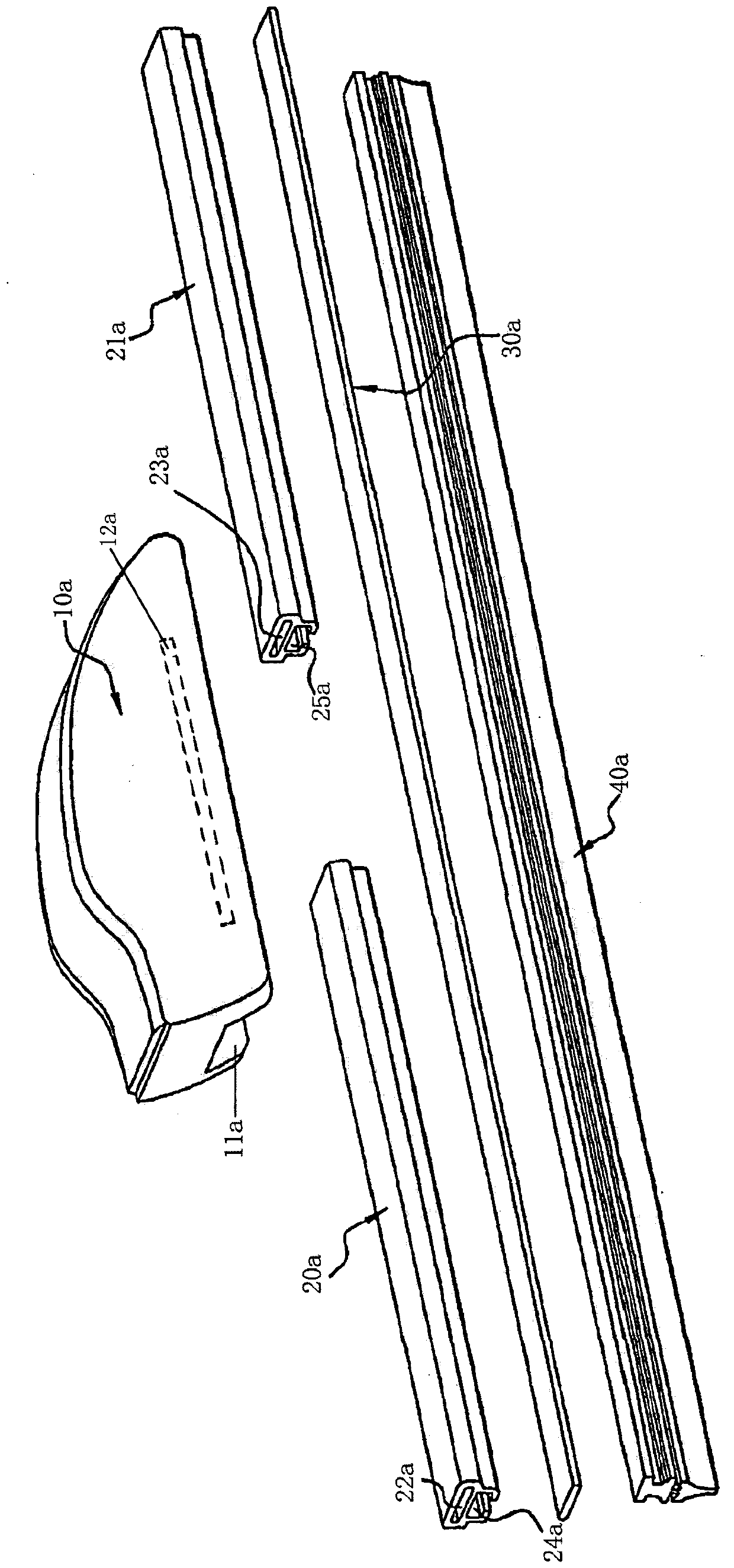
As the patent publication number is CN1984803A disclosed a kind of boneless wiper for motor vehicles, such as figure 1 As shown, the bearing splints 20a and 21a are respectively located on both sides of the wiper joint 10a, and are inserted into the lower part of the wiper joint 10a and the seat cavity 11a through which it penetrates for positioning. In the seat cavity 11a of the joint 10a and the seat cavity 23a of the bearing splint 21a, the wiper rubber strip 40a is sequentially placed on the guide rail 24a of the bearing splint 20a, the guide rail 12a of the wiper joint 10a and the guide rail 25a of the bearing splint 21a. With this structure, Since the bearing splints 20a, 21a adopt segmented design, the wiper rubber strip 40a cannot be guaranteed to be seamlessly connected at the junction of the receiving pieces 20a, 21a and the wiper joint 10a, and generally a small step surface will be generated, thus affecting the wiper rubber strip 40a. The wiping effect of strip 40a affects
Method used
Image
Click on the blue label to locate the original text in one second.
Reading with bidirectional positioning of images and text.
Examples
no. 1 example
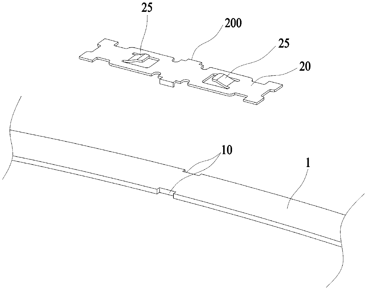
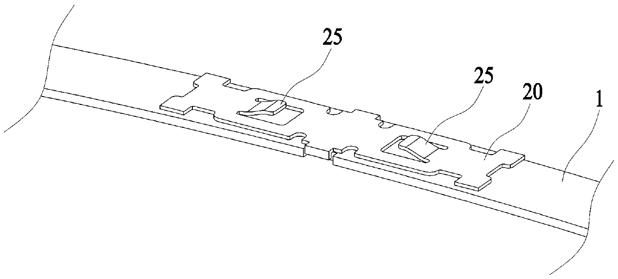
[0052] Such as figure 2 , 3 As shown, a wiper elastic support member 1, the wiper elastic support member 1 is a sheet body, the upper surface of which is additionally provided with a positioning elastic piece 20, the positioning elastic piece 20 is in the shape of a sheet, and its upper surface has stoppers 25, 26, The limiting portion is a pair of upturned flaps 25, 26, and the longitudinal sections of the two upturned flaps 25, 26 are in the shape of a figure-of-sight or an inverted figure-of-sight (inverted figure-of-sight is not shown). The middle part of the two sides of the positioning elastic piece 20 forms a first bent portion 200 downwards, and the wiper elastic support member 1 opposite to the first bent portion 200 forms a corresponding fixing notch 10, and the positioning elastic piece 20 passes through the aforementioned The first bending portion 200 of the wiper is engaged with the fixing notch 10 of the elastic supporting member 1 of the wiper.
no. 2 example
[0054] Such as Figure 4 , 5 As shown, the structure of this embodiment is basically the same as that of the first embodiment, and only the second bending part 210 is formed downward on the two sides of the positioning elastic piece 21, and is located at the front and rear ends of the two sides. The wiper elastic supporting part 1 opposite to the part 210 forms a corresponding fixing notch 11 , and the positioning elastic piece 21 is engaged with the fixing notch 11 of the wiper elastic supporting part 1 through the aforementioned second bending part 210 .
no. 3 example
[0056] Such as Figure 6 , 7 As shown, the structure of this embodiment is basically the same as that of the first embodiment, only the third bending portion 220 is formed downward at the front and rear ends of the positioning elastic piece 22, and the wiper elastic support member opposite to the third bending portion 210 1 forms a corresponding fixing notch 12, and the positioning elastic piece 22 is engaged with the fixing notch 12 of the wiper elastic supporting member 1 through the aforementioned third bending portion 220.
PUM
Abstract
The invention discloses a novel wiper elastic support part (1). The wiper elastic supporting part (1) is a piece-shaped body, positioning shrapnel (20, 21, 22, 23, 24) is additionally arranged on theupper surface of the wiper elastic supporting part (1), the positioning shrapnel (20, 21, 22, 23, 24) is in the shape of a thin sheet, and at least one limiting block (25, 26, 27) extending upwards isarranged on the upper surface of the positioning shrapnel (20, 21, 22, 23, 24). By adopting the wiper elastic supporting part (1), a load-bearing clamping piece (2) which is provided with the wiper elastic supporting part (1) in a penetrating mode is conveniently arranged in a wiper joint base (3) matched with the load-bearing clamping piece (2) in a penetrating mode, the limiting blocks (25, 26,27) on the positioning shrapnel (20, 21, 22, 23, 24) are used for being positioned and matched mutually with positioning parts (32,33) of the wiper joint base (3), at the point, the load-bearing clamping piece (2) does not need to be treated in sections, it is ensured that a scraping strip (5) can be fully arranged in the load-bearing clamping piece (2) a penetrating mode, and the scraping effectof a wiper is improved.
Description
technical field [0001] The invention relates to the field of wipers, in particular to a wiper elastic support part, a wiper base matched with the wiper elastic support part, and a wiper made of the wiper elastic support part and the wiper base. Background technique [0002] The boneless wiper generally includes a load-bearing splint, a wiper joint, an elastic support part, a wiper rubber strip and two end buckles; the load-bearing splint is used for installing the elastic support part and the wiper rubber strip. An end buckle for fixing the bearing splint, the elastic supporting part and the wiper rubber strip is provided. As the patent publication number is CN1984803A disclosed a kind of boneless wiper for motor vehicles, such as figure 1 As shown, the bearing splints 20a and 21a are respectively located on both sides of the wiper joint 10a, and are inserted into the lower part of the wiper joint 10a and the seat cavity 11a through which it penetrates for positioning. In ...
Claims
Application Information
Patent Timeline
Application Date:The date an application was filed.
Publication Date:The date a patent or application was officially published.
First Publication Date:The earliest publication date of a patent with the same application number.
Issue Date:Publication date of the patent grant document.
PCT Entry Date:The Entry date of PCT National Phase.
Estimated Expiry Date:The statutory expiry date of a patent right according to the Patent Law, and it is the longest term of protection that the patent right can achieve without the termination of the patent right due to other reasons(Term extension factor has been taken into account ).
Invalid Date:Actual expiry date is based on effective date or publication date of legal transaction data of invalid patent.

