Scraping structure of spray scraping machine

A technology of nozzles and scrapers, which is applied in the field of scraping structures of nozzle scrapers, can solve problems such as poor scraping effect, inability to fully clean the scraping block 14, and loss of cleaning agent, so as to improve the scraping effect and prolong the cleaning time. Longevity and wear-reducing effect

Active Publication Date: 2007-08-08
AU OPTRONICS CORP
View PDF0 Cites 7 Cited by
  • Summary
  • Abstract
  • Description
  • Claims
  • Application Information

AI Technical Summary

Problems solved by technology

However, due to the geometry of the scraping block 14, when the cleaning agent is sprayed on the scraping block 14, the cleaning agent w

Method used


Image

  • Scraping structure of spray scraping machine
  • Scraping structure of spray scraping machine
  • Scraping structure of spray scraping machine

Examples


Embodiment Construction

[0033] In order to have a further understanding and understanding of the structural features and the achieved effects of the present invention, a preferred embodiment and accompanying drawings will be described in detail, as follows:

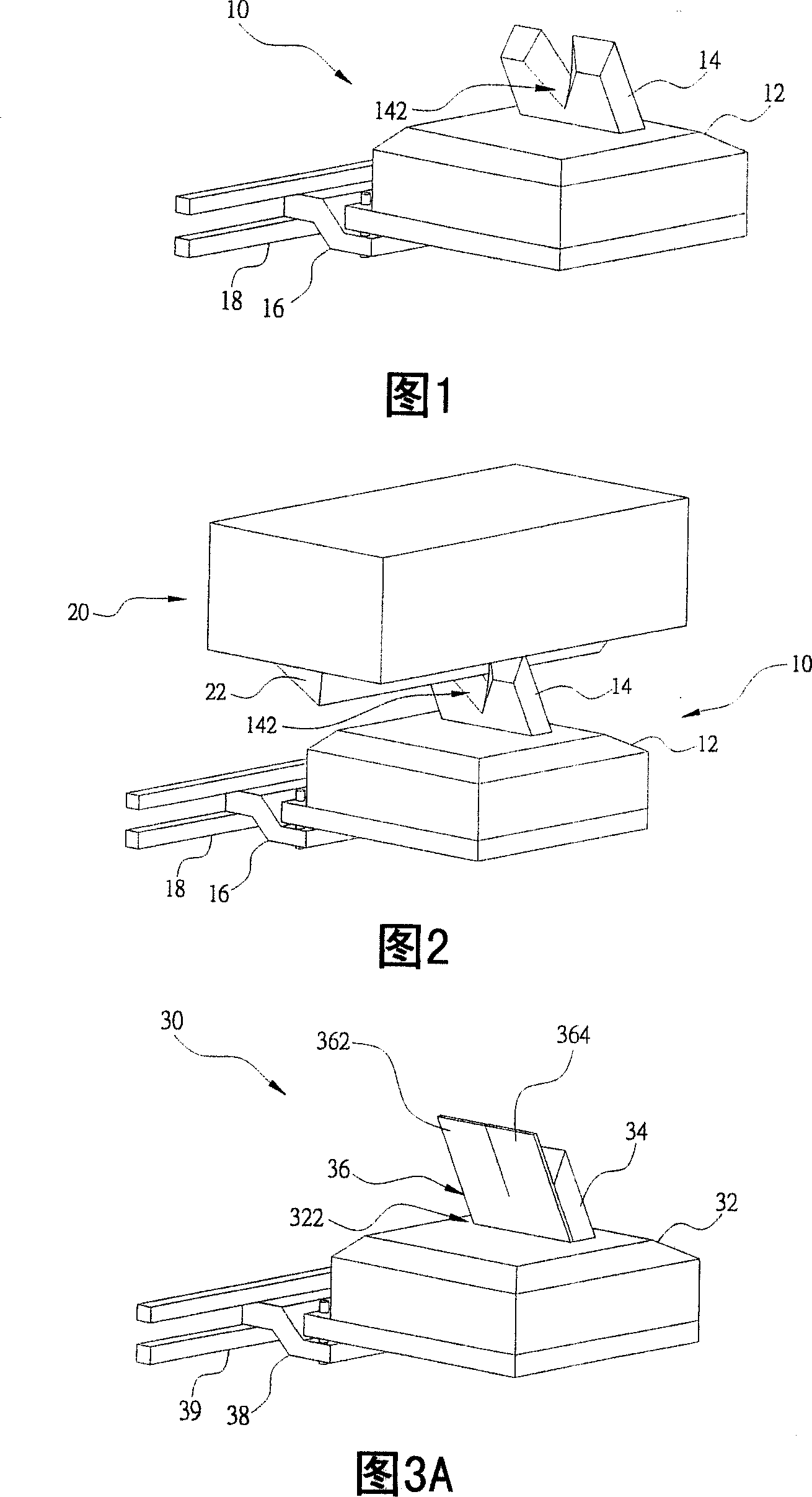
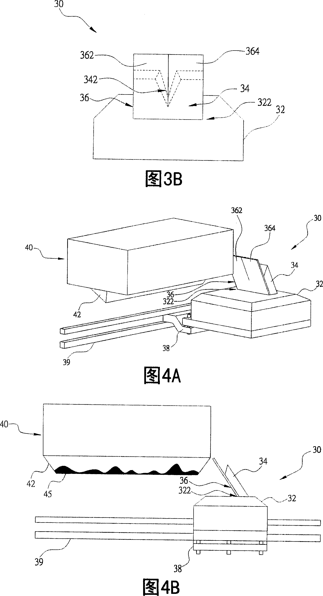
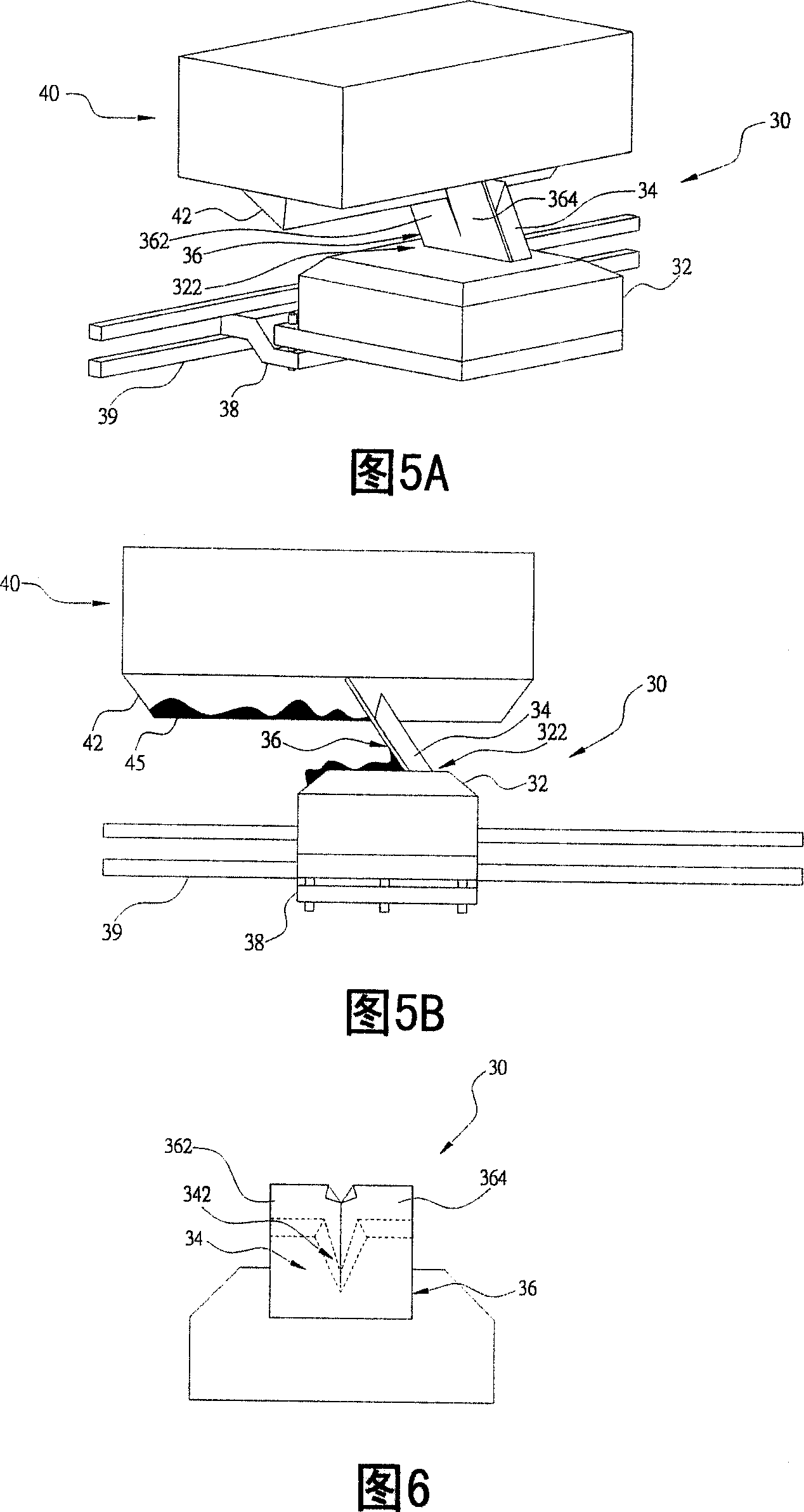
[0034] The invention relates to a scraping structure of a nozzle scraping machine, which improves the scraping effect of scraping coating material and gel remaining on the outside of a nozzle through a scraping piece and a scraping block. Moreover, the invention reduces the abrasion caused by scraping off the gel by the scraper block through the scraper sheet, thereby prolonging the service life of the scraper block.

[0035] Please refer to FIG. 3A and FIG. 3B , which are respectively a perspective view and a front view of a scraping structure of a preferred embodiment of the present invention; as shown in the figure, the scraping structure 30 of the present invention includes a base 32 and a scraping block 34 and a scraper 36. The base 32 is ...


PUM


Abstract

The scraping structure of a nozzle scraper comprises a substrate, a scraping block and a scraping blade, with the scraping block inside the substrate and having a scraping slot, the scraping blade at the front of the scraping block to increase the scraping area of the gel left on the nozzle. It can effectively improve the scraping effect, avoiding the impact to processing quality due to left gel on the nozzle, to improve the production qualification rate, reduce consumption to the scraping block and extend the durability of the scraping block.

Description

technical field [0001] The invention relates to a nozzle scraper, in particular to a scraper structure of the nozzle scraper. Background technique [0002] Currently, most industrial productions have coating processes to coat a coating material on a substrate, such as mask processes in optical disk processing and semiconductor processing. The coating process is to use a coating machine to spray the coating material to the substrate through a nozzle, so as to coat the coating material on the substrate. Taking the masking process as an example, the photoresist is coated on the substrate through the nozzle of the coater to form a mask on the substrate. When the nozzle of the coater sprays the coating material onto the substrate, the coating material remains outside the nozzle outlet and gradually forms crystals, ie, gel, over time. Since the coating machine will generate force during the coating process, such as the force generated by the spraying of the coating material from...

Claims


Application Information

Patent Timeline
IPC IPC(8): B05B15/04B05B1/28
Inventor 丁振原
Owner AU OPTRONICS CORP
Why Eureka
Try Eureka