
Workshop across material transfer equipment

A technology of over-span and material, applied in the field of over-the-cross material transfer equipment in workshop, it can solve the problems of small size, complicated and cumbersome transfer process, inconvenient transfer, etc.

Pending Publication Date: 2018-09-28
NUCLEON XINXIANG CRANE
View PDF0 Cites 4 Cited by
  • Summary
  • Abstract
  • Description
  • Claims
  • Application Information

AI Technical Summary

Problems solved by technology

[0002] With the establishment of the company's assembly line, the work efficiency and product quality of each position on the assembly line have been greatly improved. The transfer process of the U-shaped trough single beam on the production line mainly includes: U-shaped trough over-span transfer, inclined cover plate over-span transfer, Cross-span transfer of end beams and cross-span transfers of main beam ribs, where the size of end beams and main beam ribs is relatively small, and can be transferred from one station to the next with a forklift, while U-shaped grooves, The slanted cover plate is an integral cold-rolled workpiece, which is a slender workpiece with a large size and a long length, so it is inconvenient to use a forklift for transportation
In the past, the transfer method of workpieces such as U-shaped grooves and inclined covers was mainly to use one span crane to lift, and then use another span crane to lift and transport. The transfer process was complicated and cumbersome.
[0003] In order to solve the cumbersome problem of the U-shaped trough transfer process, a workshop cross-span material transfer equipment has been developed for the cross-span large-scale material transfer

Method used


Image

  • Workshop across material transfer equipment
  • Workshop across material transfer equipment
  • Workshop across material transfer equipment

Examples


Embodiment Construction

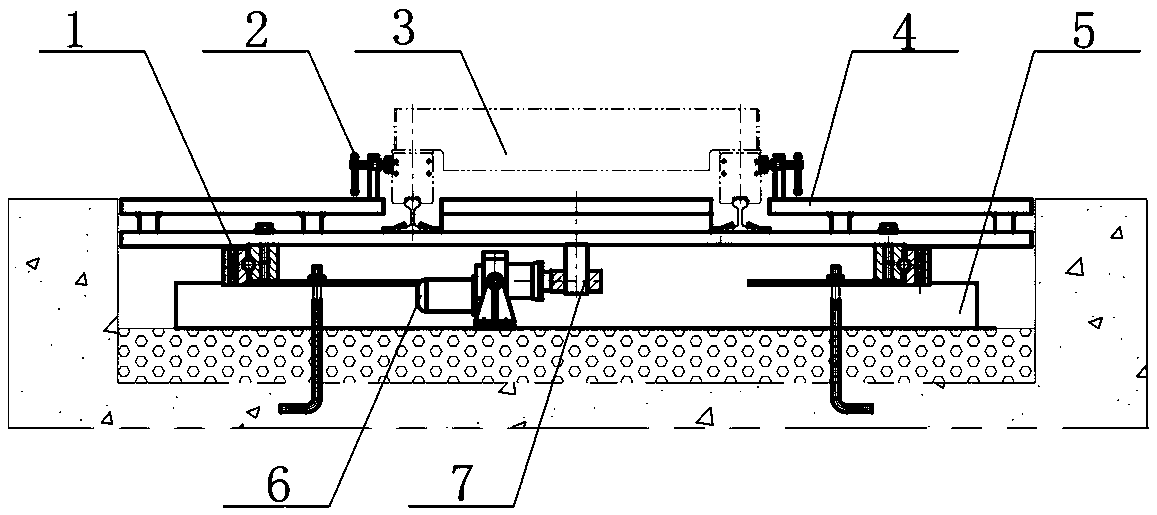
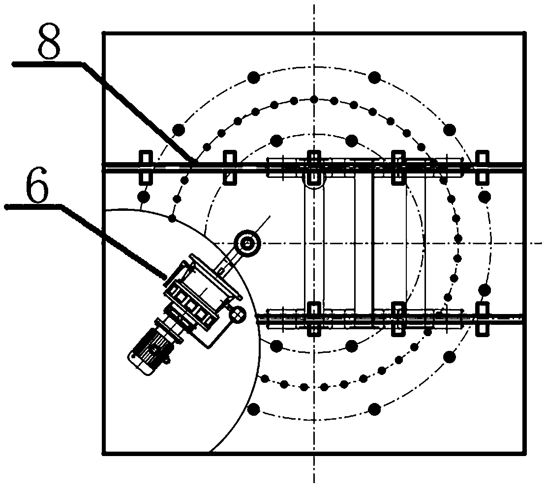
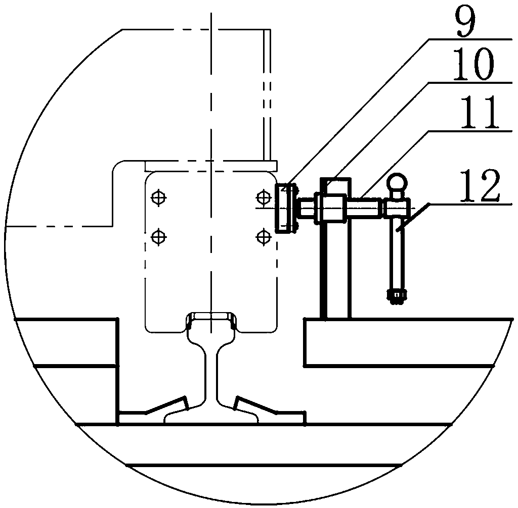
[0016] as attached Figure 1-5 As shown, the cross-span material transfer equipment in the workshop includes a docking track 8, a turntable 4, a slewing support 1, a fixed seat 5, an electro-hydraulic push rod 6, and a hinge shaft 7; the docking track 8 is set on the turntable 4, and the turntable 4 passes through the The slewing support 1 is placed on the fixed seat 5, and the electro-hydraulic push rod 6 is installed on the lower part of the turntable 4 through the hinge shaft 7, wherein the hinge shaft 7 is installed on the non-central part of the turntable 4, and the controller controls the electro-hydraulic push rod.

[0017] The rotation angle of the turntable 4 is controlled by the telescopic length of the electro-hydraulic push rod 6, and the transfer vehicle 3 docked on the docking track 8 on the upper side of the turntable 4 is adjusted to enable the transfer vehicle 3 to realize cross-span transfer. The electro-hydraulic push rod 6 is used to push the eccentric part...


PUM


Abstract

The invention discloses workshop across material transfer equipment which comprises a butt connection track, a rotary table, a rotary support, a fixed base, an electric-hydraulic push rod and a hingeshaft. The butt connection track is arranged on the rotary table, the rotary table is placed on the fixed base through the rotary support, the electric-hydraulic push rod is installed on the lower portion of the rotary table through the hinge shaft, the hinge shaft is installed on the non-center portion of the rotary table, and a controller controls the electric-hydraulic push rod. Compared with the prior art, across transfer for large workpieces is achieved, a material transfer trolley can stably operate, the transfer trolley can be carried to be rotated accurately by a certain angle, the transfer trolley transfers materials to a designated area, and reciprocating transfer of teams or group and material storage areas on an assembly line is achieved.

Description

technical field [0001] The invention relates to workshop cross-transfer of materials, in particular to a workshop cross-transfer equipment. Background technique [0002] With the establishment of the company's assembly line, the work efficiency and product quality of each position on the assembly line have been greatly improved. The transfer process of the U-shaped trough single beam on the production line mainly includes: U-shaped trough over-span transfer, inclined cover plate over-span transfer, Cross-span transfer of end beams and cross-span transfers of main beam ribs, where the size of end beams and main beam ribs is relatively small, and can be transferred from one station to the next with a forklift, while U-shaped grooves, The inclined cover plate is an integral cold-rolled workpiece, which is a slender workpiece with a large size and a long length, and it is inconvenient to use a forklift for transfer. In the past, the transfer method of workpieces such as U-shape...

Claims


Application Information

Patent Timeline
Patent Type & Authority Applications(China)
IPC IPC(8): B65G47/64B65G35/00
CPCB65G35/00B65G47/644
Inventor 金庆好李静宇董瑞丽王京伟祝艺菘施晓玲
Owner NUCLEON XINXIANG CRANE
Learn More