Adjustable brake device

A braking device and adjustable technology, applied in the direction of mechanical drive drum brakes, gear shifting mechanisms, mechanical equipment, etc., can solve the problem of inconvenient adjustment of braking force, and achieve the effect of convenient adjustment of braking force and avoid repeated measurement.

Active Publication Date: 2018-09-28
WUHAN MARINE MACHINERY PLANT
View PDF5 Cites 1 Cited by
  • Summary
  • Abstract
  • Description
  • Claims
  • Application Information

AI Technical Summary

Problems solved by technology

[0006] In order to solve the problem in the prior art that it is inconvenient for users to adjust the braking force, the embodiment of the present invention provides an adjustable braking device

Method used


Image

  • Adjustable brake device
  • Adjustable brake device
  • Adjustable brake device

Examples


Embodiment Construction

[0023] In order to make the object, technical solution and advantages of the present invention clearer, the implementation manner of the present invention will be further described in detail below in conjunction with the accompanying drawings.

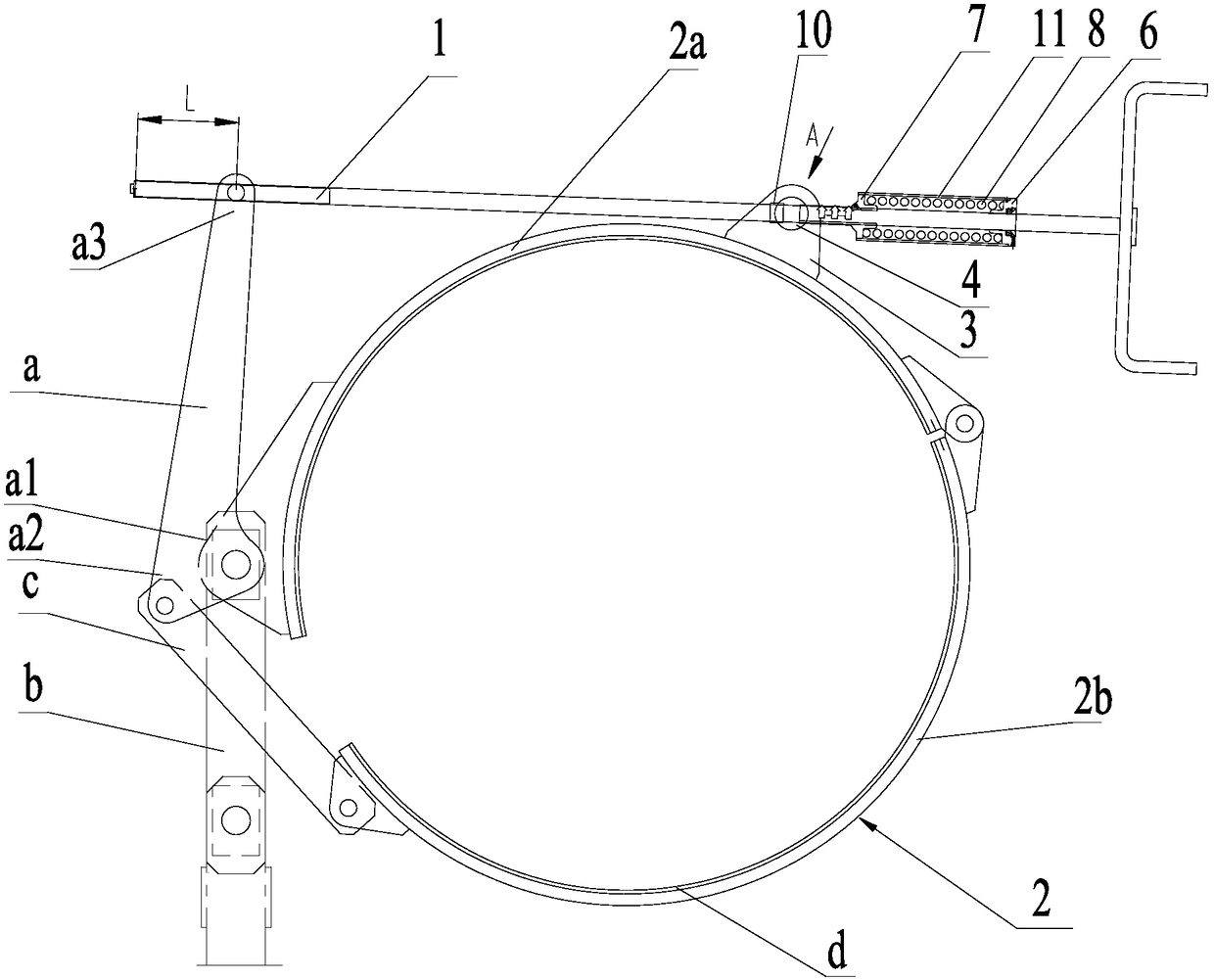
[0024] The embodiment of the present invention provides an adjustable braking device, such as figure 1 As shown, the adjustable brake device includes a control rod 1, a first pull plate a, a second pull plate b, a connecting rod c, a brake band 2 and two ear plates 3 fixed on the brake band 2, and the brake band 2 includes The first sub-brake band 2a and the second sub-brake band 2b, the first sub-brake band 2a and the second sub-brake band 2b are respectively provided with brake pads d, one end of the first sub-brake band 2a and the second sub-brake band 2b One end of the first pull plate a is a triangular plate, and the other end of the first sub-brake band 2a is hinged at the first corner a1 of the first pull plate a; one end of the...


PUM


Abstract

The invention discloses an adjustable brake device and belongs to the field of band brake devices. The adjustable brake device also comprises a first mounting seat, a second mounting seat, an elasticresetting part and a brake force indicator, wherein the first mounting seat is mounted on a control rod; the second mounting seat is slidably arranged on the control rod in a sleeving manner, and thesecond mounting seat is arranged between a limiting pin and the first mounting seat; one end of the elastic resetting part is mounted on the first mounting seat while the other end of the elastic resetting part is mounted on the second mounting seat; the brake force indicator is arranged along the direction of the control rod and is fixed to a lug plate; and scales corresponding to the brake forces are arranged on the brake force indicator. Both the first mounting seat and the second mounting seat are arranged closer to a user relative to a first pulling plate, so that the user is prevented from rushing about back and forth at two ends of the control rod, and therefore, the adjustable brake device brings convenience to the user for adjusting the brake force.

Description

technical field [0001] The invention relates to the field of band brake devices, in particular to an adjustable brake device. Background technique [0002] As a common brake device, band brakes are widely used on offshore platforms. [0003] There is an existing band brake device, which includes a control rod, a first pull plate, a second pull plate, a connecting rod, a brake band and a brake pad. The brake band includes a first sub-brake band and a second sub-brake band. On the first sub-brake band and the second sub-brake band, one end of the first sub-brake band is hinged to one end of the second sub-brake band; the first pull plate is a triangular plate, and the other end of the first sub-brake band is hinged At the first vertex of the first pull plate; one end of the second pull plate is hinged with the first vertex of the first pull plate; one end of the connecting rod is fixed at the second vertex of the first pull plate; The other end is connected with the other en...

Claims


Application Information

Patent Timeline
Patent Type & Authority Applications(China)
IPC IPC(8): F16D49/04F16D125/68
CPCF16D49/04F16D2125/68
Inventor 白福余
Owner WUHAN MARINE MACHINERY PLANT
Why Eureka
Try Eureka