Cement culvert pipe laying method for building engineering

A technology of construction engineering and laying method, which is applied in pipeline laying and maintenance, construction, and sewer pipeline systems, etc., can solve the problems of large laying workload, high laying cost, and heavy design weight of cement culverts, and achieve the effect of ensuring stability.

Active Publication Date: 2018-09-28
广东长海建设工程有限公司
View PDF5 Cites 12 Cited by
  • Summary
  • Abstract
  • Description
  • Claims
  • Application Information

AI Technical Summary

Problems solved by technology

[0003] Cement culvert pipes are indispensable in the application of construction engineering, and cement culvert pipes cannot be directly processed into the required length due to their heavy design weight. They are usually processed according to the national rated length and laid according to the quantity. Cement culvert pipes are laid one by one during the laying process of cement culvert pipes. The current laying method is generally to choose manual laying and hoisting air crane for laying. The laying process is heavy and requires large-scale hoisting equipment. The laying cost is high. It can be seen that there is a need for a special laying equipment for laying cement culvert pipes

Method used


Image

  • Cement culvert pipe laying method for building engineering
  • Cement culvert pipe laying method for building engineering
  • Cement culvert pipe laying method for building engineering

Examples


Embodiment 1

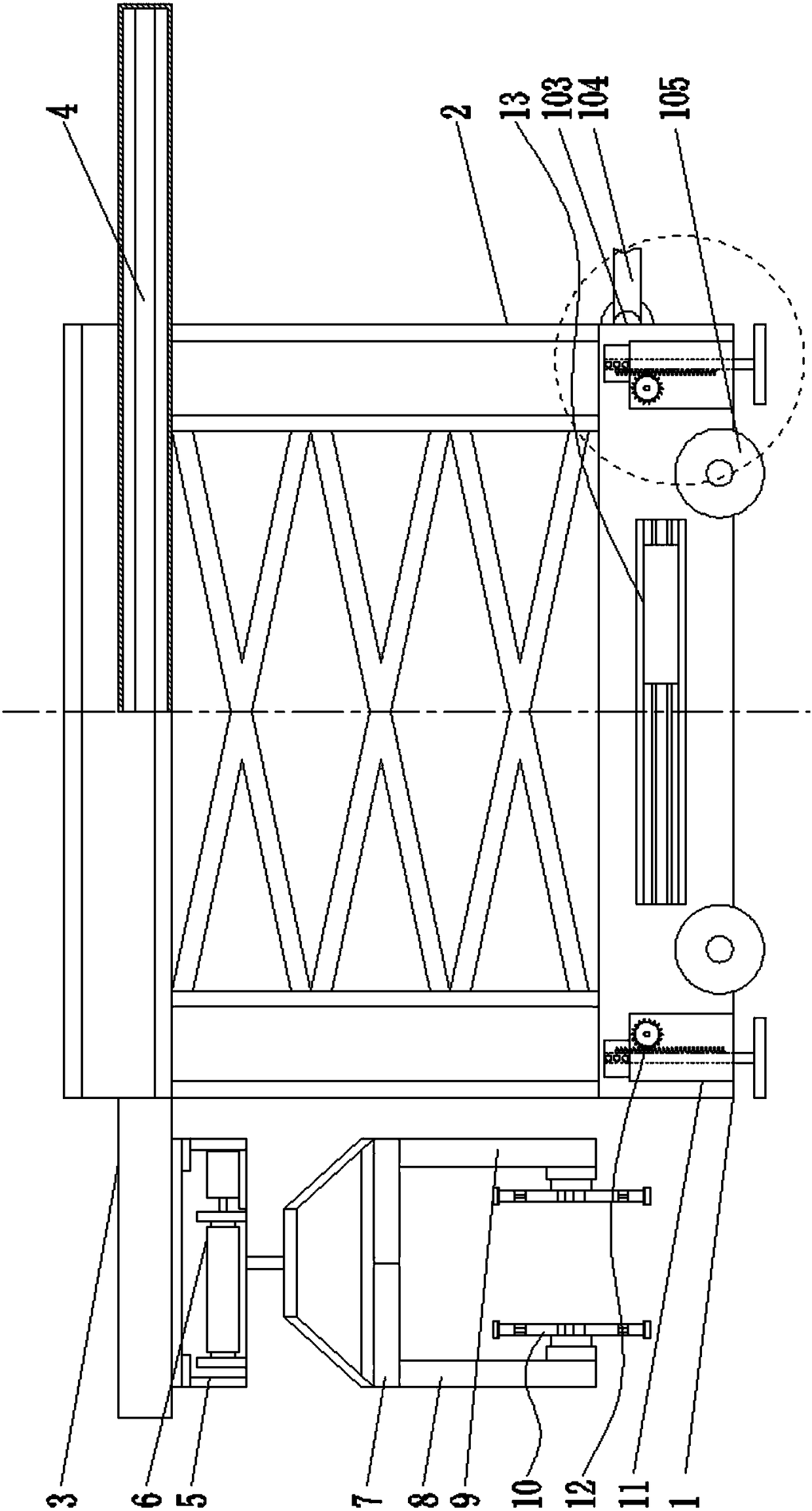
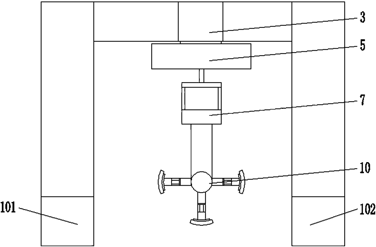
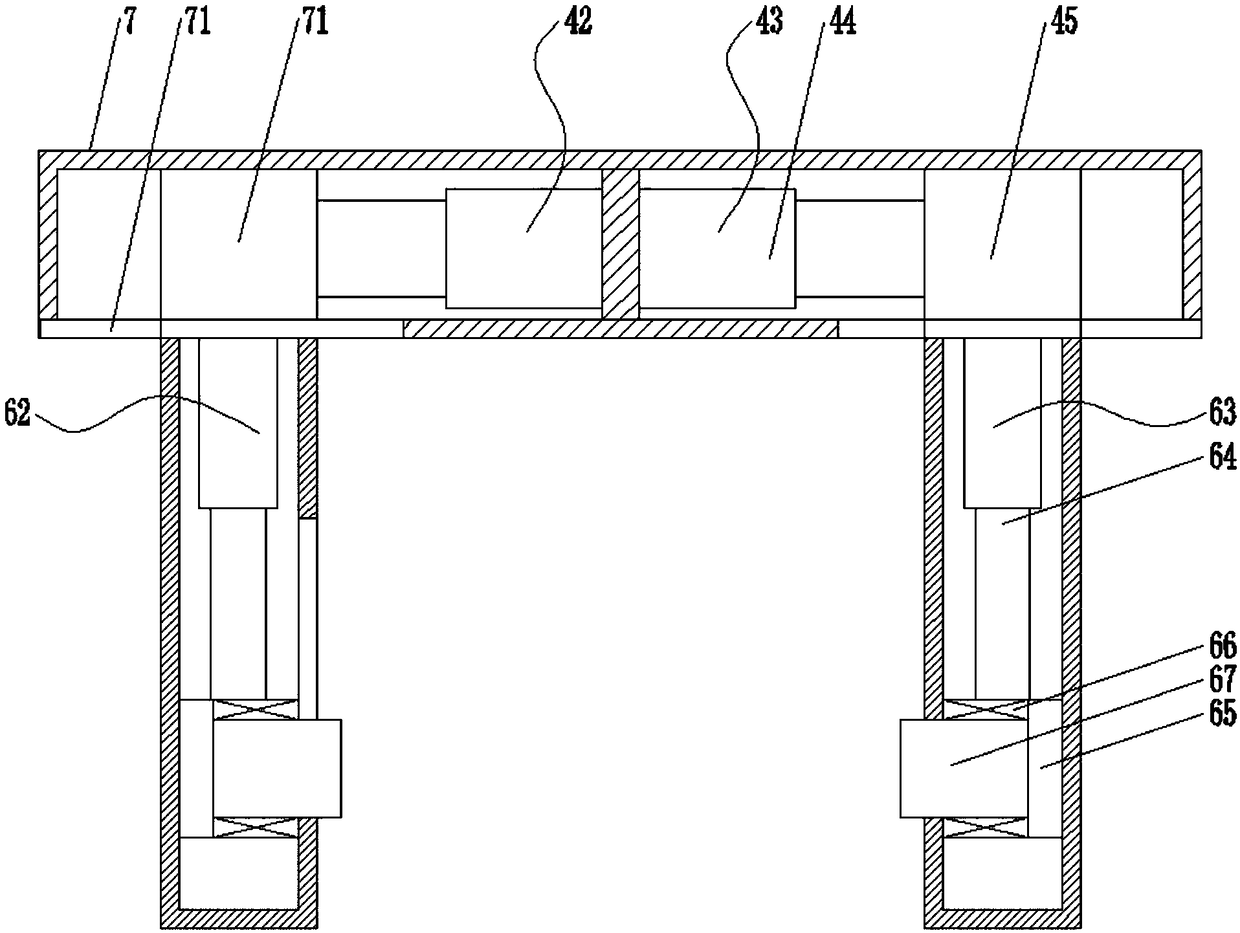
[0044] combine Figure 1-Figure 9 , Figure 14-Figure 15 As shown, a cement culvert pipe laying device disclosed in this embodiment includes: a mobile body 1, an installation frame 2, a supporting beam 3, a first mobile driving device 4, a hoisting frame 5, a first lifting driving device 6, Fixed beam 7, the first fixed vertical beam 8, the second fixed vertical beam 9 and the culvert fixing device 10; the mobile body 1 comprises a first mobile body 101 and a second mobile body 102, the first mobile body 101 and the The front end of the second mobile body 102 is respectively fixedly provided with a set of mounting lugs 103, and the mounting lugs 103 are fixedly connected with a set of body connecting arms 104 through a rotating shaft, and the other end of the body connecting arm 104 can be connected to the carrying vehicle of the cement culvert pipe. To disassemble the connection, the lower ends of the first mobile body 101 and the second mobile body 102 are respectively prov...

Embodiment 2

[0048] Different from Embodiment 1, the stent fixing device 10 can also include three sets of fixed support arms 1001, and the stroke angles between the three sets of fixed support arms are 120°.

Embodiment 3

[0050] Such as Figure 11-13Shown on the basis of Embodiment 1, the first mobile drive device 4 in this embodiment includes a first drive housing 401, and a drive motor 402 is arranged in the first drive housing 401, and the drive motor 402 The main shaft is fixedly connected with the first driving screw 403 through a coupling, and a group of screw nuts are arranged on the first driving screw 403, and a moving slider 404 is set on the outer end of the screw nut, and the first driving screw 403 The lower end of the drive housing 401 is processed with a moving waist-shaped groove 405 corresponding to the size of the moving slider 404. The moving slider 404 passes through the moving waist-shaped groove 405 and is fixedly connected with the hoisting frame 5. The moving The other three end surfaces of the slider 404 are respectively provided with a set of sliding protrusions 406, and the inner end surface of the first driving housing 401 is processed with a moving chute correspondi...


PUM


Abstract

The invention relates to the technical field of building engineering machines, in particular to a cement culvert pipe laying method for building engineering. According to the cement culvert pipe laying method, a moving machine body is included; and a mounting frame is arranged on the moving machine body, a supporting cross beam is fixedly arranged on the mounting frame, a first moving driving device is arranged in the supporting cross beam, the movable end of the first moving driving device is fixedly connected with a hoisting frame, the hoisting frame is internally provided with a first lifting driving device fixedly connected with a fixing cross beam, the fixing cross beam is internally provided with a second moving driving device and a third moving driving device, and the second movingdriving device and the third moving driving device are each provided with a set of culvert pipe fixing device. According to the cement culvert pipe laying method, a plurality of sets of transverse moving devices and the lifting driving device are matched with the culvert pipe fixing devices, cement culvert pipes are unloaded from a carrying vehicle and then directly laid without assisting of a large machine, and the laying cost is greatly reduced.

Description

technical field [0001] The invention relates to the field of construction engineering equipment, in particular to a method for laying cement culvert pipes for construction engineering. Background technique [0002] Cement culvert pipe is a kind of preset pipe made of cement and steel bars, using the principle of centrifugal force of utility poles; cement culvert pipe is also called cement pressure pipe, reinforced concrete pipe, it can be used as a sewer pipe in urban construction foundation, and can be drained Sewage, flood control and drainage, as well as water pipes and farm wells used in some special factories and mines. It is generally divided into: flat reinforced concrete cement culvert, flexible tongue and groove reinforced concrete cement culvert, socket reinforced concrete cement culvert, F-shaped steel socket cement culvert, flat collar interface cement culvert, tongue and groove cement culvert, etc.; [0003] Cement culvert pipes are indispensable in the applica...

Claims


Application Information

Patent Timeline
Patent Type & Authority Applications(China)
IPC IPC(8): F16L1/024B66C1/56B66C15/00B66C19/00E03F3/06
CPCB66C1/445B66C1/56B66C15/00B66C19/00E03F3/06F16L1/024
Inventor 闫丽华
Owner 广东长海建设工程有限公司
Why Eureka
Try Eureka