Cement culvert pipe laying device for construction engineering
A technology for construction engineering and laying devices, which is applied to water supply devices, buildings, sewer pipe systems, etc., can solve the problems of heavy laying workload, heavy design weight of cement culvert pipes, and high laying costs, and achieve the effect of ensuring stability
- Summary
- Abstract
- Description
- Claims
- Application Information
AI Technical Summary
Problems solved by technology
Method used
Image
Examples
Embodiment 1
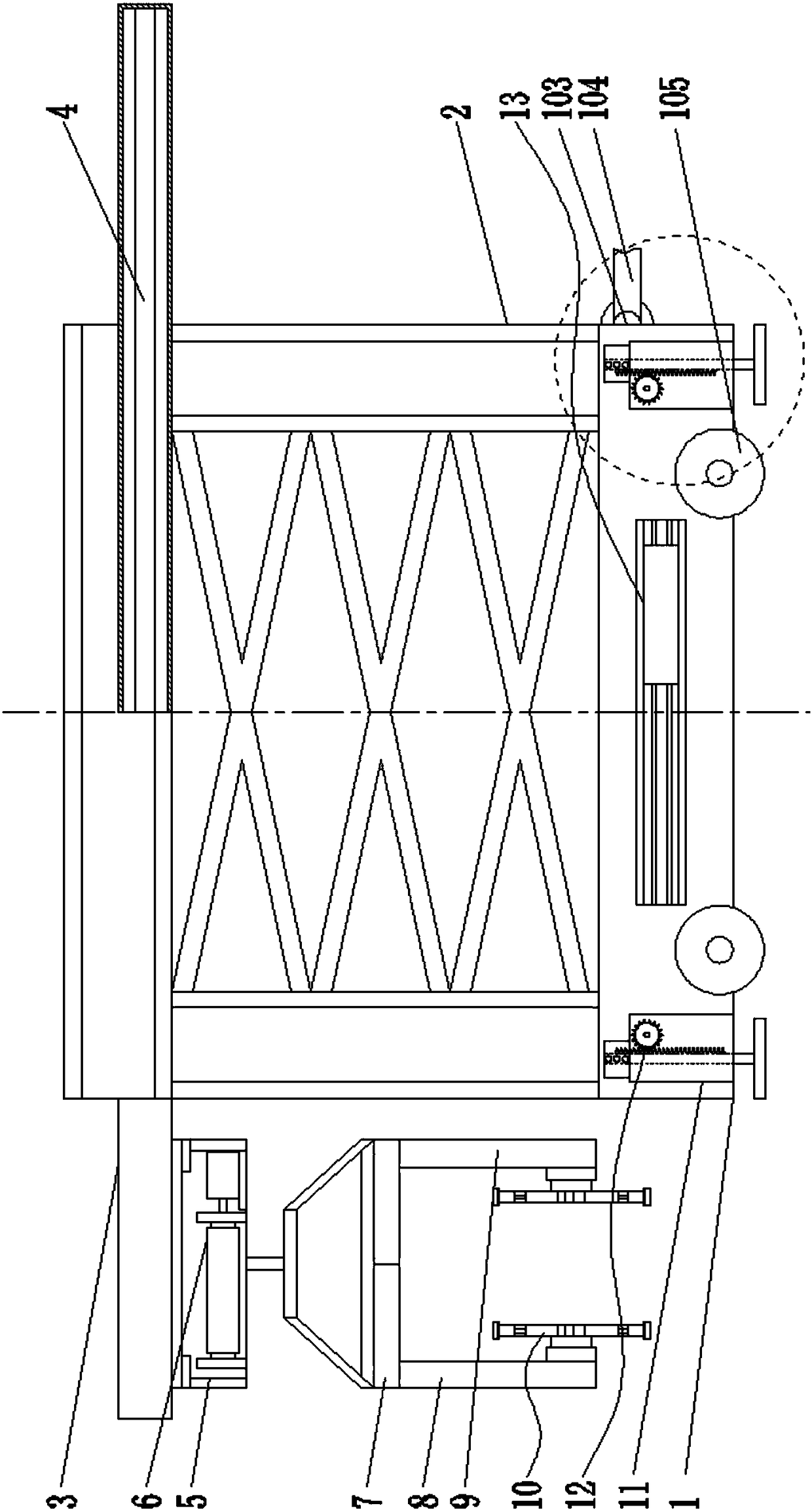
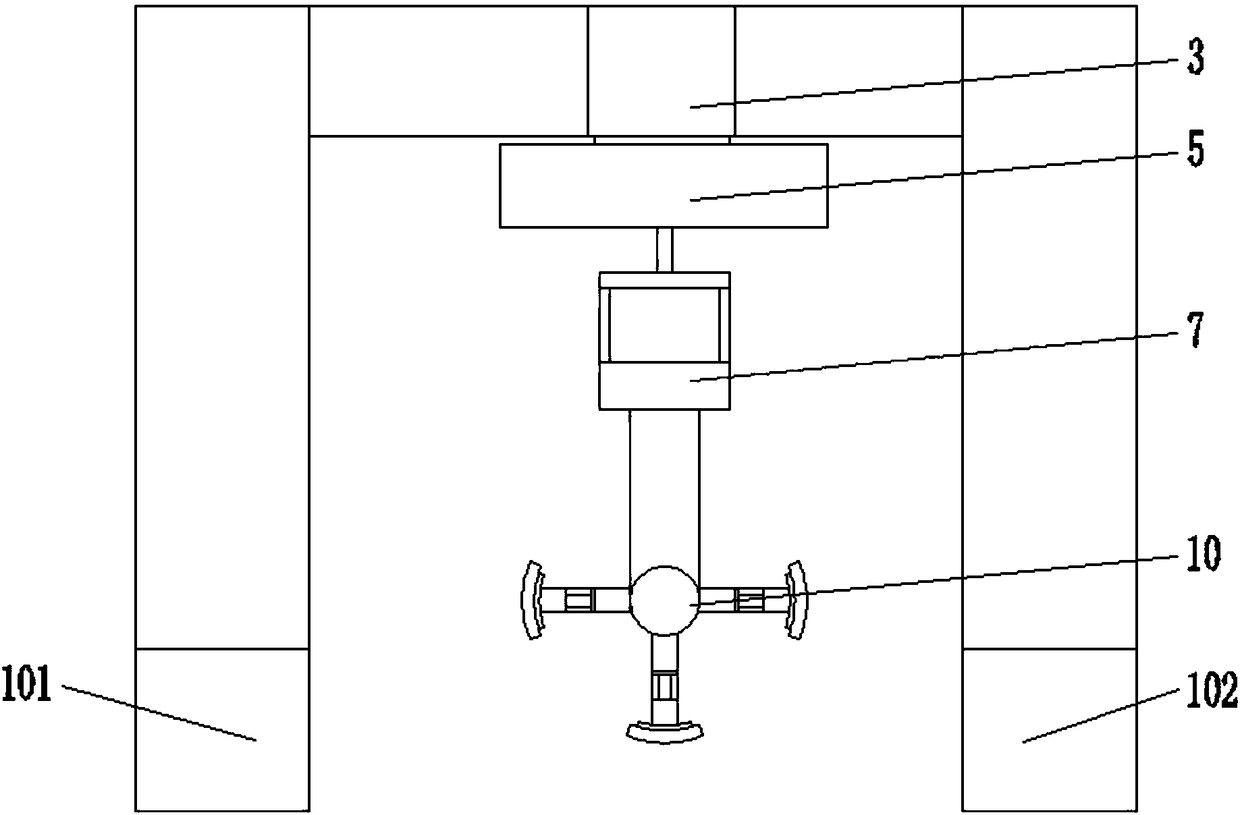
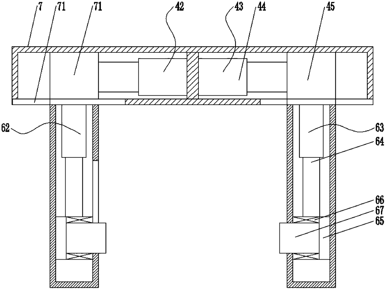
[0044] combine Figure 1-Figure 9 , Figure 14-Figure 15 As shown, a cement culvert pipe laying device disclosed in this embodiment includes: a mobile body 1, an installation frame 2, a supporting beam 3, a first mobile driving device 4, a hoisting frame 5, a first lifting driving device 6, Fixed beam 7, the first fixed vertical beam 8, the second fixed vertical beam 9 and the culvert fixing device 10; the mobile body 1 comprises a first mobile body 101 and a second mobile body 102, the first mobile body 101 and the The front end of the second mobile body 102 is respectively fixedly provided with a set of mounting lugs 103, and the mounting lugs 103 are fixedly connected with a set of body connecting arms 104 through a rotating shaft, and the other end of the body connecting arm 104 can be connected to the carrying vehicle of the cement culvert pipe. To disassemble the connection, the lower ends of the first mobile body 101 and the second mobile body 102 are respectively prov...
Embodiment 2
[0048] Different from Embodiment 1, the stent fixing device 10 can also include three sets of fixed support arms 1001, and the stroke angles between the three sets of fixed support arms are 120°.
Embodiment 3
[0050] Such as Figure 11-13Shown on the basis of Embodiment 1, the first mobile drive device 4 in this embodiment includes a first drive housing 401, and a drive motor 402 is arranged in the first drive housing 401, and the drive motor 402 The main shaft is fixedly connected with the first driving screw 403 through a coupling, and a group of screw nuts are arranged on the first driving screw 403, and a moving slider 404 is set on the outer end of the screw nut, and the first driving screw 403 The lower end of the drive housing 401 is processed with a moving waist-shaped groove 405 corresponding to the size of the moving slider 404. The moving slider 404 passes through the moving waist-shaped groove 405 and is fixedly connected with the hoisting frame 5. The moving The other three end surfaces of the slider 404 are respectively provided with a set of sliding protrusions 406, and the inner end surface of the first driving housing 401 is processed with a moving chute correspondi...
PUM
 Abstract
Description
Claims
Application Information
 - R&D
- Intellectual Property
- Life Sciences
- Materials
- Tech Scout
- Unparalleled Data Quality
- Higher Quality Content
- 60% Fewer Hallucinations
Browse by: Latest US Patents, China's latest patents, Technical Efficacy Thesaurus, Application Domain, Technology Topic, Popular Technical Reports.
© 2025 PatSnap. All rights reserved.Legal|Privacy policy|Modern Slavery Act Transparency Statement|Sitemap|About US| Contact US: help@patsnap.com


