[0058] (first embodiment)
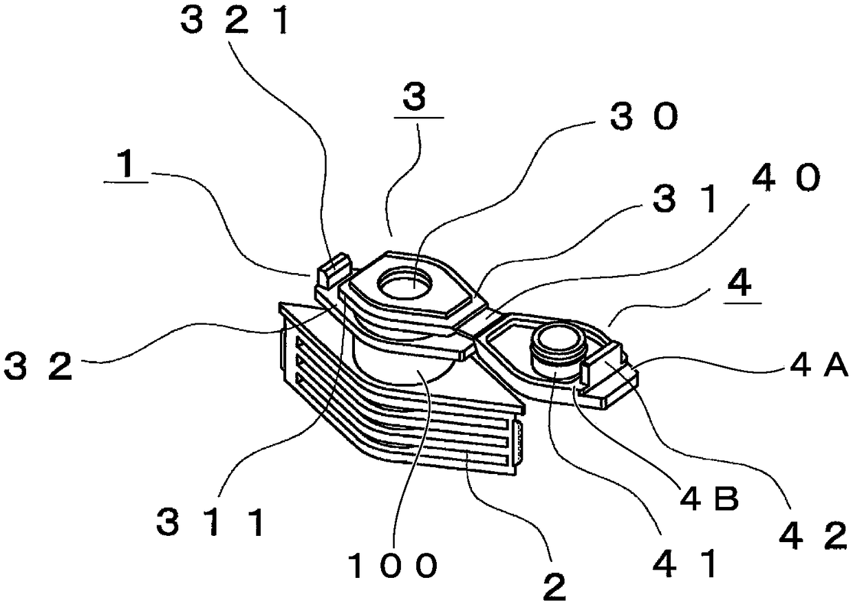
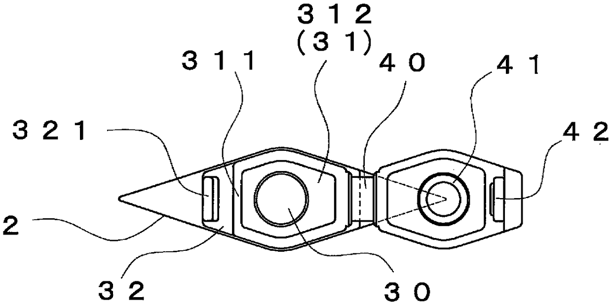
[0059] figure 1 It is a perspective view which shows the external appearance of the stopper which concerns on the 1st Embodiment of this invention.
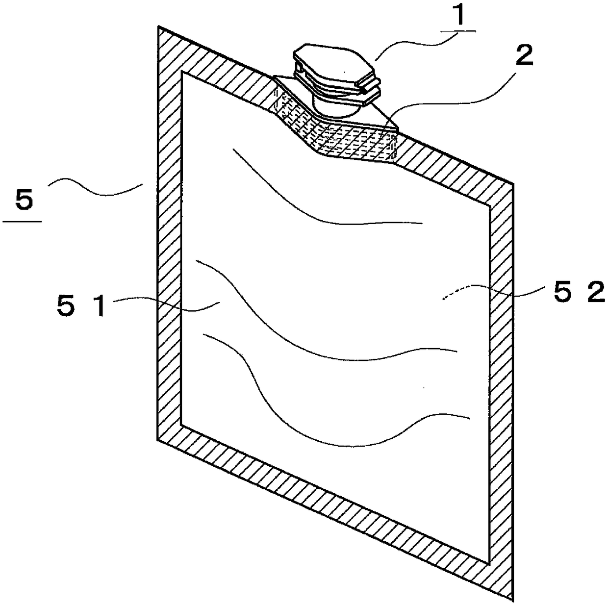
[0060] figure 2 It is a figure which shows the case of using the film container to which the stopper spout which concerns on 1st Embodiment of this invention is welded, and is a perspective view which shows the external appearance of the film container.
[0061] Usually, the mouthpiece according to the first embodiment of the present invention is injection-molded to have figure 1 manufactured in the shape shown in the perspective view. The stopper 1 is used by being welded to one end of the film container 50 . The spout 1 has a welded portion 2 located below the spout 1 . In order to facilitate the welding of the film and the plug 1, the welding portion 2 is formed in a boat shape in which the outer shape in the longitudinal direction is tapered to the left and right and the center is swollen in a circular arc in a plan view. Furthermore, the spout 1 has the outflow port 3 located above the spout 1 .
[0062] The stopper 1 has an outflow hole 30 provided inside the stopper 1 so as to penetrate the welded portion 2 and the outflow port 3 described above. The outflow hole 30 is provided so as to penetrate the inside and outside of the film container 50 . In addition, two flanges (a first flange 31 and a second flange 32 ) are provided around the outflow port 3 .
[0063] Among the two flanges, the first flange 31 is located around the foremost end of the outflow port 3 , and is connected to the hinge cap 4 which can open and close the outflow port 3 in a press-fit manner via the hinge portion 40 . Further, the first flange 31 is provided with an engaging protrusion 311 (engaging rib) on the side opposite to the position of the hinge portion 40 .
[0064] Furthermore, the second flange 32 is provided below the first flange 31 . The second flange 32 is provided with a pressing rib 321 at a position facing the engaging protrusion 311 . The pressing rib 321 serves to prevent the hinge pin cover 4 engaged with the engaging protrusion 311 from being easily opened due to impact or the like.
[0065] The hinge pin cover 4 is provided with an inner ring 41 which is located in the center of the hinge pin cover 4 and is inserted into the outflow hole 30 of the outflow port 3 . The hinge pin cover 4 is provided with an engaging claw 42 on the side opposite to the hinge portion 40 . Furthermore, in the hinge bolt cover 4, the thickness of the front end portion 4A on the outer side of the engagement claw 42 is smaller than the thickness of the hinge bolt cover main body 4B (the part other than the front end portion 4A and the thickness of the outer shape of the hinge bolt cover 4) .
[0066] With this structure, in a state where the spout 1 is closed (for example, refer to later-described Figure 6A ), the front end portion 4A of the hinge bolt cover 4 and the corner portion 321C of the pressing rib 321 ( Figure 4A and Figure 6A A sufficient space R can be obtained between the reference). Therefore, as will be described later, the user can easily confirm the position of the front end portion 4A of the hinge cap 4 and the user's fingernails or fingers can easily and sufficiently touch the front end 4A of the hinge cap 4 .
[0067] As described above, the welded portion 2 formed in the boat shape is sandwiched between the front film 51 and the back film 52 of the film body 5 constituting the film container 50 and welded. Therefore, the outflow hole 30 of the stopper 1 is welded with a gap provided between the front film 51 and the back film 52 . Usually, as figure 2 As shown in the perspective view of , the hinge cap 4 is closed, the inner ring 41 provided on the inner wall of the hinge cap 4 is inserted into the inside of the outflow hole 30, and the film container 50 is sealed.
[0068] Next, the structure of the stopper 1 will be described more specifically.
[0069] 3A to 3C It is a figure which shows the stopper 1 which concerns on the 1st Embodiment of this invention, and shows the state just after injection-molding the stopper. Figure 3A is a plan view showing the spout 1, Figure 3B is a front view showing the spout 1, Figure 3C It is a left side view which shows the stopper 1.
[0070] like Figure 3B and Figure 3C As shown, the spout 1 includes a spout body 100 , a first flange 31 , a hinge cap 4 , and a second flange 32 .
[0071] The spout body 100 has the outflow port 3 , the outflow hole 30 communicating with the outflow port 3 , and the outflow hole protrusion 301 (inner wall protrusion) provided on the inner wall W of the outflow hole 30 .
[0072] The first flange 31 includes an engaging protrusion 311 protruding outward from the nozzle body 100 , and a hinge portion 40 located on the opposite side of the engaging protrusion 311 . The first flange 31 is provided at a position adjacent to the outflow port 3 on the outer side of the spout body 100 .
[0073] The hinge pin cover 4 includes a hinge pin cover main body 4B connected to the first flange 31 via the hinge portion 40 , an engagement claw 42 capable of engaging with the engagement protrusion 311 , and insertable into the outflow hole 30 via the outflow port 3 . The inner ring 41, the inner ring engaging protrusion 411 provided on the inner ring 41 and capable of engaging with the outflow hole protrusion 301, and the front end portion 4A having a thickness smaller than that of the hinge bolt cover main body 4B and located outside of the engaging claw 42 .
[0074] The second flange 32 includes an extension portion 322 that protrudes outward from the nozzle body 100 and is provided at a position farther from the outlet 3 than the first flange 31 , and a pressing rib 321 that protrudes from the front end of the extension portion 322 , and is provided at a position facing the engaging protrusion 311 , and can be brought into contact with the engaging pawl 42 .
[0075] A boat-shaped welding part 2 is provided at the lowermost position of the plug nozzle 1, and the boat-shaped welding part 2 is shown in a plan view ( Figure 3A ) has a boat-like shape that tapers to the left and right.
[0076] On the outer surface of the welded boat 2, a sink mark preventing recess 21 extending in the lateral direction is formed to prevent the surface of the welded boat 2 from shrinking (depressed) due to molding and reducing the welding force. In addition, the ribs 22 tapered at the front end are thinly provided at the left and right ends of the boat-shaped welded portion 2, and are designed so that no gap is formed at the boundary line where the front film 51 and the back film 52 begin to overlap.
[0077] A second flange 32 is disposed above the boat-shaped welded portion 2 , and a pressing rib 321 is disposed on the left end of the second flange 32 . Furthermore, the first flange 31 is arranged above the second flange 32 . The outflow hole 30 provided in the center of the 1st flange 31 penetrates the 1st flange 31, the 2nd flange 32, and the fusion part 2 so that it may reach the lower end of the fusion part 2.
[0078] The pressing rib 321 is provided in the left end part of the 2nd flange 32 (extension part 322) so that it may protrude from the upper surface of the 2nd flange 32 to the upper direction in the vertical direction. In this configuration, the space S surrounded by the second flange 32 , the pressing rib 321 , and the engaging protrusion 311 is formed.
[0079]An engaging protrusion 311 is provided on the left end of the first flange 31 . The right end portion of the first flange 31 is provided with a hinge portion 40 connected to the hinge bolt cover 4 . In addition, in the first flange 31 , the upper surface of the portion (step portion 312 ) located around the opening of the outflow hole 30 is slightly higher than the upper surface of the first flange 31 (the upper surface of the engaging protrusion 311 ). The stepped portion 312 is separated from the outer circumference of the first flange 31 by a constant width, and is located inward of the outer circumference of the first flange 31 . like Figure 3B As shown, by forming the stepped portion 312 higher than the upper surface of the first flange 31, the closed state of the hinge bolt cover 4 can be confirmed without greatly changing the folded position of the hinge portion. In addition, in this embodiment, as Figure 3A and Figure 3B As shown, the step portion 312 is formed in the first flange 31, but the step portion 312 may not be provided in the present invention.
[0080] Furthermore, in the hinge pin cover 4 connected to the first flange 31 by the hinge part 40 , an inner ring 41 located at the center of the hinge pin cover 4 is provided. Furthermore, on the side opposite to the hinge portion 40 with respect to the inner ring 41 , an engagement claw 42 that engages with the engagement protrusion 311 is provided. Protrusions 421 are formed on surfaces (protrusion surfaces) of the engaging pawls 42 facing the inner ring 41 .
[0081] An inner ring engaging protrusion 411 is provided in a band shape on the outer periphery of the inner ring 41 . In addition, on the side opposite to the hinge portion 40 with respect to the engaging claw 42 ( Figure 3B ), a front end portion 4A (step difference) having an upper surface lower than the upper surface of the hinge bolt cover main body 4B is provided. As will be described later, by providing the front end portion 4A, the user's fingernails and the like can easily enter between the hinge cap 4 and the first flange 31, and the cap can be easily opened.
[0082] Figure 4A and Figure 4B It is a figure which shows the front-end|tip of the outflow port 3 of the stopper 1 which concerns on the 1st Embodiment of this invention. Figure 4A It is an enlarged longitudinal cross-sectional view showing a state in which the hinge bolt cover 4 is opened. On the outer periphery of the inner ring 41 located at the center of the hinge bolt cover 4, an inner ring engaging protrusion 411 is provided. In addition, an outflow hole protrusion 301 is also provided on the inner wall of the outflow hole 30 . Furthermore, an inclined surface 321A (chamfered) is provided on the inner surface 321D (surface facing the engaging protrusion 311 ) of the pressing rib 321 provided on the second flange 32 . The inner side surface 321D faces the engaging protrusion 311 . The inclined surface 321A is provided at the end of the inner surface 321D.
[0083] In the present embodiment, the thickness of the second flange 32 is defined by T1 (thickness in the direction perpendicular to the extending direction of the second flange 32 ). The thickness of the pressing rib 321 is defined by T2 (thickness in the direction parallel to the extending direction of the second flange 32). The thickness of the hinged cover 4 is defined by T3. In this embodiment, the thickness T2 is larger than the thickness T1 (T2>T1). Further, the thickness T2 is larger than the thickness T3 (T2>T3). More specifically, when linear low-density polyethylene is selected as the material of the spigot 1, for example, the thickness T1 is 1.25 mm, the thickness T2 is 1.40 mm, and the thickness T3 is 1.00 mm. In addition, the thicknesses T1, T2, and T3 listed in the present embodiment are merely examples of the present invention, and the values of the above-mentioned thicknesses can be appropriately changed as long as the thickness conditions “T2>T1” and “T2>T3” are satisfied. .
[0084] By defining the thickness T1 of the second flange 32 , the thickness T2 of the pressing rib 321 , and the thickness T3 of the hinge cap 4 in this way, the function of the pressing rib 321 described later can be sufficiently obtained, and the user can open the cap 1 while The hinge bolt cover 4 is opened while elastically deforming the hinge bolt cover 4 .
[0085] Figure 4B It is an enlarged longitudinal sectional view showing a state in which the hinge cap 4 is closed. if from Figure 4A When the hinge portion 40 is bent by 180 degrees from the open state of the hinge pin cover 4 shown to be in the closed state of the hinge pin cover 4 , the inner ring 41 is inserted into the outflow hole 30 . At this time, since the hinge bolt cover 4 is rotated about the center of the hinge portion 40 as a base point, the front end of the inner ring 41 is provided with a curved surface so that the inner ring 41 can be easily inserted into the outflow hole 30 . When the inner ring 41 is inserted into the outflow hole 30, the inner ring engaging protrusion 411 is engaged with the outflow hole protrusion 301, and a click feeling can be obtained. Furthermore, the engaging claw 42 provided on the hinge bolt cover 4 is engaged with the engaging protrusion 311 provided on the opposite side of the hinge portion 40 in the first flange 31 . At this time, the lower end of the engaging protrusion 311 is in contact with the protrusion 421 . In this way, even when the engaging claws 42 engage with the engaging protrusions 311, at the same time as the engagement between the inner ring engaging protrusions 411 and the outflow hole protrusions 301, the front ends (protrusions 421) of the engaging claws 42 pass over the engaging protrusions 311 and proceed. Therefore, a stronger click feeling can be obtained. At this time, the pressing rib 321 is adjacent to the surface (back surface of the engagement pawl 42 ) opposite to the engagement surface (protrusion surface) of the engagement pawl 42 engaged with the engagement projection 311 . In other words, the front end of the engagement claw 42 is arranged in the space S. As shown in FIG.
[0086] Next, refer to Figure 5A and Figure 5B , the state in which the plug mouth 1 is closed by the hinge plug cover 4 will be specifically described.
[0087] Figure 5A This is a longitudinal cross-sectional view showing a state in which the internal pressure of the plug nozzle 1 is increased and the hinge plug cover 4 starts to open in a state where the plug nozzle 1 is closed by the hinge plug cover 4 .
[0088] Figure 5B This is a partial cross-sectional view showing a state in which the hinge cap 4 starts to open when the film container including the cap 1 is dropped while the cap 1 is closed by the hinge cap 4 . in particular, Figure 5A and Figure 5B It is an enlarged view which shows the member in the vicinity of the outflow port 3. FIG.
[0089] like Figure 5A As shown, in the film container 50 provided with the spout 1 according to the first embodiment of the present invention, the user may unintentionally hold the bag portion of the film container 50 strongly. In this case, the internal pressure of the film-made container 50 in which the content is sealed rises, and as indicated by the reference numeral P, a force for opening the hinge cap 4 is generated. Alternatively, as the temperature of the use environment of the film container 50 changes, the content in the film container 50 expands, the internal pressure of the film container 50 rises, and as indicated by the reference sign P, the hinge pin may be generated. The force with which cover 4 is opened.
[0090] In this case, with the generation of the force P from the outflow hole 30 toward the outside of the hinge bolt cover 4 , the hinge bolt cover 4 is pressed to the upper side of the outflow port 3 . Therefore, the hinge bolt cover 4 is about to rotate around the hinge portion 40 . Thereby, the member on the opposite side to the hinge portion 40 (the engaging claw 42 ) that is not connected to the hinge portion 40 tends to move above the outflow port 3 first. In addition, the portion 411A of the inner ring engaging protrusion 411 of the inner ring 41 on the opposite side to the hinge portion 40 is about to go over the outflow hole protrusion 301 . When a force to open the hinge bolt cover 4 acts in this way, the outflow hole 30 expands outward so that the wall W1 (inner wall) of the outflow hole 30 opposite to the hinge portion 40 is pushed outward. Therefore, the engaging protrusion 311 provided on the opposite side of the hinge portion 40 of the first flange 31 is also deformed so as to be pushed out. With the deformation of the engaging protrusion 311, the engaging pawl 42 is moved outward ( Figure 5A the left side) is pushed out of the way deformed. When the engaging claw 42 is pushed out, the outer surface 42A of the engaging claw 42 comes into contact with the inner surface 321D of the pressing rib 321 provided on the second flange 32 . The pressing rib 321 restricts the outward deformation of the engaging claw 42 , and prevents the engaging claw 42 from moving to the outside beyond the surface where the pressing rib 321 is in contact with the engaging claw 42 . Therefore, even when the pressure inside the film container 50 is rapidly increased due to the application of pressure from the outside, or the content of the film container 50 expands due to the temperature change of the environment in which the film container 50 is used, the inside of the film container 50 In the case of increased pressure, the hinged cover 4 will not be easily opened.
[0091] Furthermore, if Figure 5B As shown, in the film container 50 provided with the spout 1 according to the first embodiment of the present invention, the user may drop the film container 50 unintentionally and the spout 1 may hit the ground.
[0092] In this way, if the drop impact of the film-made container 50 is applied to the cap 1, the hinge cap 4 may try to rotate around the hinge portion 40 due to vibration or the like. In this case, the member (the engaging claw 42 ) on the opposite side to the hinge portion 40 which is not connected to the hinge portion 40 is about to move downward (toward the falling surface FL) of the outflow port 3 first. In addition, the portion 411A of the inner ring engaging protrusion 411 of the inner ring 41 on the opposite side to the hinge portion 40 is about to go over the outflow hole protrusion 301 . When a force to open the hinge bolt cover 4 acts in this way, the outflow hole 30 expands outward so that the wall W1 of the outflow hole 30 on the opposite side to the hinge portion 40 is pushed outward. Therefore, the engaging protrusion 311 provided on the opposite side of the hinge portion 40 of the first flange 31 is also deformed so as to be pushed out. With the deformation of the engaging protrusion 311, the engaging pawl 42 is moved outward ( Figure 5B the right side) is pushed out of the way deformed. When the engaging claw 42 is pushed out, the outer surface 42A of the engaging claw 42 comes into contact with the inner surface 321D of the pressing rib 321 provided on the second flange 32 . The pressing rib 321 restricts the outward deformation of the engaging claws 42 and prevents the engaging claws 42 from moving outward from the surface where the pressing rib 321 contacts the engaging claws 42 . Therefore, even if a drop shock is applied to the cap 1 due to the drop of the film-made container 50, the hinge cap 4 is not easily uncapped.
[0093] especially in Figure 4A , Figure 5A and Figure 5B Among them, the thickness T1 of the second flange 32 and the thickness T2 of the pressing rib 321 satisfy the condition “T2>T1”, so the strength of the inverted L-shaped structure composed of the second flange 32 and the pressing rib 321 can be sufficiently obtained, Unintentional opening of the hinge bolt cover 4 by the user can be reliably prevented.
[0094] Next, refer to 6A to 6C , the operation of the spout 1 when the user opens the hinge cap 4 which is closed relative to the spout 1 will be specifically described.
[0095] Figure 6A It is a longitudinal sectional view showing a state before the user opens the hinge bolt cover. Figure 6B It is a longitudinal sectional view showing a state where a user applies force to open the hinge bolt cover. Figure 6C It is a longitudinal sectional view showing a state in which the hinge bolt cover is opened.
[0096] In the following description, the case where the user opens the hinge plug cover 4 with the pulp of the finger F will be described, but the same applies to the case where the user opens the hinge plug cover 4 with a fingernail.
[0097] First, as Figure 6A As shown, the thickness of the front end portion 4A is smaller than the thickness of the hinge bolt cover main body 4B, so that a sufficient space R can be obtained between the front end portion 4A of the hinge bolt cover 4 and the corner portion 321C of the pressing rib 321 .
[0098] When the hinge pin cover 4 is opened, the user makes the pulp of the finger F abut the front end portion 4A of the hinge pin cover 4 . At this time, the user's finger F may contact not only the distal end portion 4A but also the outer surface 321B of the pressing rib 321 . That is, in this case, the user's finger F covers the space R between the corner portion 321C of the outer surface 321B and the front end portion 4A. When the finger F touches the distal end portion 4A and the corner portion 321C, the user can confirm the position of the distal end portion 4A. In addition, since the outer surface 321B is flat, the user can confirm the position of the distal end portion 4A while sliding the finger F on the outer surface 321B.
[0099] Next, as Figure 6BAs shown, after the user confirms the position of the front end portion 4A, a force for pulling the front end portion 4A upward is applied to the hinge cap 4 . Here, since a sufficient space R is formed between the front end portion 4A of the hinge pin cover 4 and the corner portion 321C of the pressing rib 321 , between the front end portion 4A of the hinge pin cover 4 and the corner portion 321C of the pressing rib 321 In the space R between, the finger pulp of the user's finger F can be easily hooked to the front end portion 4A. Therefore, the user can easily open the hinge latch cover 4 by pulling the front end portion 4A upward while pressing the front end portion 4A of the hinge latch cover 4 . At this time, when the finger F is in contact with the outer surface 321B, the user can pull up the front end portion 4A upward while sliding the finger F on the outer surface 321B.
[0100] Also, when the front end portion 4A is opened by the user's fingernail, the user's fingernail easily enters the space R, and the hinge cap 4 can be easily opened by pulling up the front end portion 4A with the fingernail.
[0101] The operation of opening the hinge bolt cover 4 will be specifically described.
[0102] When the user applies a force to the hinge bolt cover 4 to pull up the front end portion 4A, the elastic deformation of the hinge bolt cover 4 starts. When the user gradually pulls up the front end portion 4A upward, the elastic deformation region X gradually increases from the front end portion 4A toward the hinge portion 40 . With the increase of the elastic deformation area X, the inner ring 41 located below the elastic deformation area X is deformed, and the portion 411A of the inner ring engaging protrusion 411 of the inner ring 41 on the opposite side to the hinge portion 40 is about to go over the outflow hole protrusion 301 . When a force to open the hinge bolt cover 4 acts in this way, the outflow hole 30 expands outward so that the wall W1 of the outflow hole 30 on the opposite side to the hinge portion 40 is pushed outward. Therefore, the engaging protrusion 311 provided on the opposite side of the hinge portion 40 of the first flange 31 is also deformed so as to be pushed out. With the deformation of the engaging protrusion 311, the engaging pawl 42 is moved outward ( Figure 6B the left side) is pushed out of the way deformed. When the engaging claw 42 is pushed out to the outside, the outer surface 42A of the engaging claw 42 comes into contact with the pressing rib 321 provided on the second flange 32 .
[0103] Further, the user continues to apply a force to the hinge bolt cover 4 to pull up the front end portion 4A, whereby the elastic deformation area X further increases along with the elastic deformation of the hinge bolt cover 4 , and the outer side surface 42A of the engaging claw 42 It slides while being in contact with the inner surface 321D of the pressing rib 321 . Then, if the elastic deformation of the hinge bolt cover 4 further progresses, the outer end 42B of the engaging claw 42 reaches the inclined surface 321A, and the engaging claw 42 is disengaged from the pressing rib 321 , such as Figure 6C As shown, the hinged bolt cover 4 is removed from the bolt mouth 1 .
[0104] especially in Figure 4A , Figure 6A and Figure 6B Among them, the thickness T1 of the second flange 32 , the thickness T2 of the pressing rib 321 , and the thickness T3 of the hinge bolt cover 4 satisfy the conditions “T2>T1” and “T2>T3”. Therefore, the engagement claw 42 can be easily disengaged from the pressing rib 321 while elastically deforming the hinge pin cover 4 by the user continuously applying force to the hinge pin cover 4 .
[0105] Figure 7A It is a longitudinal cross-sectional view which shows the state of the stopper spout 1 before the hinge stopper cover 4 is closed, and is an enlarged view which shows the member located in the vicinity of the outflow port 3. FIG.
[0106] Figure 7B It is a longitudinal cross-sectional view which shows the state of the stopper spout 1 in which the hinge stopper cover 4 starts to close, and is an enlarged view which shows the member located in the vicinity of the outflow port 3. FIG.
[0107] When closing the hinge cap 4 with respect to the outflow port 3, the hinge cap 4 is rotated around the hinge portion 40, the inner ring 41 is inserted into the outflow hole 30, and the hinge cap 4 is pressed down from above. At this time, the inner ring engaging protrusions 411 provided on the inner ring 41 are pressed in by the outflow hole protrusions 301 provided on the inner wall of the outflow hole 30 and aligned to a precise position. Therefore, the upper part of the outflow hole 30 expands slightly and engages with the outflow hole 30. The protrusion 311 is pushed out to the outside. When the engagement protrusion 311 is pushed out, the engagement pawl 42 is further pushed out. However, since the inclined surface 321A is formed on the inner side surface 321D of the pressing rib 321 , the outer end 42B of the engaging claw 42 slides on the inclined surface 321A by the force acting to press the hinge bolt cover 4 from above. It is gradually pushed in toward the inside of the space S. Furthermore, the engaging claw 42 slides in and enters the lower side of the engaging protrusion 311 , and the engaging protrusion 311 and the engaging claw 42 can be engaged with each other.
[0108] Therefore, as Figure 7B As shown, the lower end of the engaging protrusion 311 is also formed with an inclined surface (chamfer), so that the engaging claw 42 can be smoothly engaged with the engaging protrusion 311 .