Compaction adjustable type electric cabinet

A technology of compression adjustment and power cabinet, which is applied in the direction of electrical components, substation/switch layout details, supporting machines, etc. It can solve problems such as the compression of equipment that cannot be installed, the instability of the outside of the power cabinet, and the impact on the efficiency of use, etc., to achieve Ensure stability, improve practicability and functionality, and facilitate adjustment

Active Publication Date: 2018-10-12
JIANGSU HAITONG ELECTRICAL APPLIANCE CO LTD
View PDF6 Cites 1 Cited by
  • Summary
  • Abstract
  • Description
  • Claims
  • Application Information

AI Technical Summary

Problems solved by technology

[0004] The purpose of the present invention is to provide a compression adjustable power cabinet to solve the problem that although the existing power cabinet proposed in the above background technology can adjust the internal space, the adjustment method needs to be manually operated, and the degree of automation is low. This affects the efficiency of use, and the power cabinet cannot well compress the installed equipment, so that external collisions will affect the use of the interior, and safety accidents are prone to occur. The outside of the power cabinet is not stable enough to pass through specific The position of the structure is limited, so the power cabinet is prone to the danger of falling

Method used


Image

  • Compaction adjustable type electric cabinet
  • Compaction adjustable type electric cabinet
  • Compaction adjustable type electric cabinet

Examples


Embodiment Construction

[0021] The following will clearly and completely describe the technical solutions in the embodiments of the present invention with reference to the accompanying drawings in the embodiments of the present invention. Obviously, the described embodiments are only some, not all, embodiments of the present invention. Based on the embodiments of the present invention, all other embodiments obtained by persons of ordinary skill in the art without making creative efforts belong to the protection scope of the present invention.

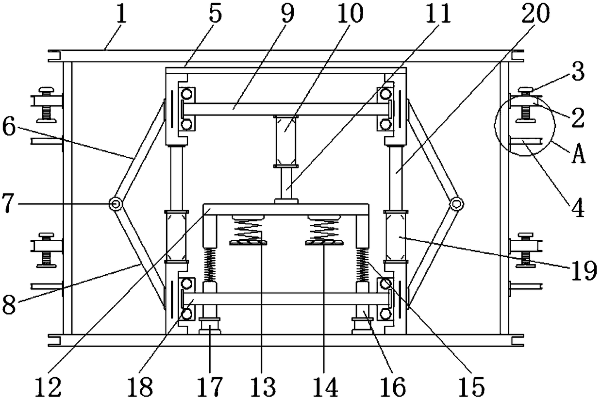
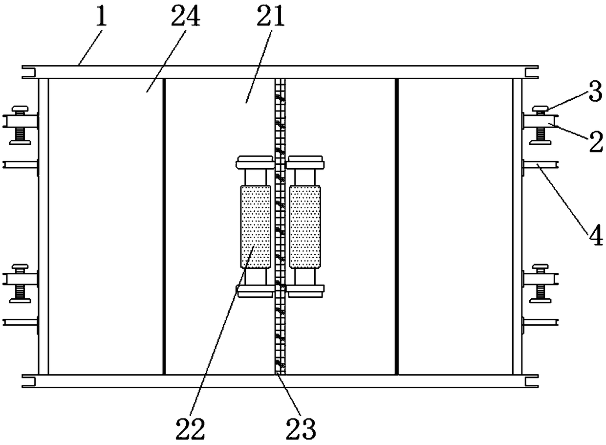
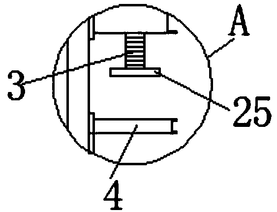
[0022] see Figure 1-5 , the present invention provides a technical solution: a compression adjustable power cabinet, including a power cabinet main body 1, a fixed block 2, a fastening bolt 3, a support block 4, a bracket 5, an upper telescopic rod 6, a rotating shaft 7, a lower Telescopic rod 8, support plate 9, first hydraulic cylinder 10, first connecting rod 11, pressing block 12, first spring 13, cushion block 14, second spring 15, pillar 16, ferrule 17,...


PUM


Abstract

The invention relates to a compaction adjustable type electric cabinet. The compaction adjustable type electric cabinet comprises an electric cabinet main body, a bracket and a second hydraulic air cylinder, wherein fixed blocks are arranged at left and right sides of the electric cabinet main body, and fastening bolts are arranged inside the fixed blocks in a penetrating mode; the bottom ends ofthe fastening bolts are equipped with fastening blocks; supporting blocks are mounted below the fastening blocks; the bracket is arranged above the inner part of the electric cabinet main body; left and right sides of the bracket are connected with upper telescopic poles; the lower portions of the upper telescopic poles are connected with lower telescopic poles through rotary shafts; a supportingplate is arranged below the bracket; a first hydraulic air cylinder is mounted below the supporting plate; and the bottom end of the first hydraulic air cylinder is connected with a first connecting rod. The compaction adjustable type electric cabinet has the beneficial effects that the fastening blocks can clamp an object by rotating the fastening bolts, so that the position of the electric cabinet can be limited through a special structure.

Description

technical field [0001] The invention relates to the technical field of power devices, in particular to a compression-adjustable power cabinet. Background technique [0002] Power cabinets, also known as safety tool cabinets, are widely used in units and departments of various voltage levels such as substations, centralized control stations, line work areas, and customer service centers of power companies. They have the function of identifying and classifying insulating tools: through identification and Classification avoids safety accidents caused by taking different types of insulating tools by mistake, and can effectively manage insulating tools with different voltages. [0003] Although the existing power cabinet can adjust the internal space, the adjustment method needs to be manually operated, and the degree of automation is low, which affects the efficiency of use, and the power cabinet cannot well compress the installed equipment, so External collisions will affect t...

Claims


Application Information

Patent Timeline
Patent Type & Authority Applications(China)
IPC IPC(8): F16M11/04F16M11/18F16M11/26F16M11/38F16M13/02H02B1/32
CPCF16M11/04F16M11/18F16M11/26F16M11/38F16M13/02H02B1/32
Inventor 冯瑞芳
Owner JIANGSU HAITONG ELECTRICAL APPLIANCE CO LTD
Why Eureka
Try Eureka