Energy-saving environment-friendly LED projection lamp

An energy-saving and environmentally-friendly technology for LED floodlights, which is applied in the field of floodlights, can solve the problems that the height of the floodlights cannot be adjusted, and the heat dissipation effect of the floodlights is poor, so as to improve the heat dissipation effect, facilitate promotion, and facilitate installation. Effect

Inactive Publication Date: 2018-10-12
WUHU CHUNYUAN PHOTOELECTRIC EQUIP TECH CO LTD
View PDF5 Cites 2 Cited by
  • Summary
  • Abstract
  • Description
  • Claims
  • Application Information

AI Technical Summary

Problems solved by technology

[0004] The object of the present invention is to provide an energy-saving and environment-friendly LED floodlight to solve the problem that the existing floodlight generally has a fixed structure with a base and a floodlight proposed in the background art, and the height of the floodlight with such a structure And the irradiation angle cannot be adjusted; in addition, the problem of poor heat dissipation of the existing floodlights

Method used


Image

  • Energy-saving environment-friendly LED projection lamp
  • Energy-saving environment-friendly LED projection lamp
  • Energy-saving environment-friendly LED projection lamp

Examples


Embodiment 1

[0024] see Figure 1-2 , the present invention provides a technical solution:

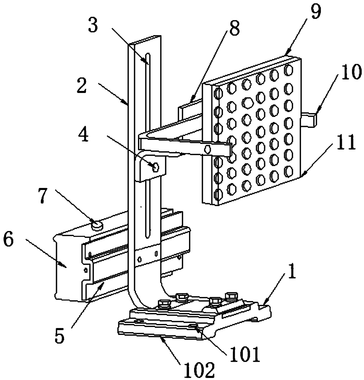
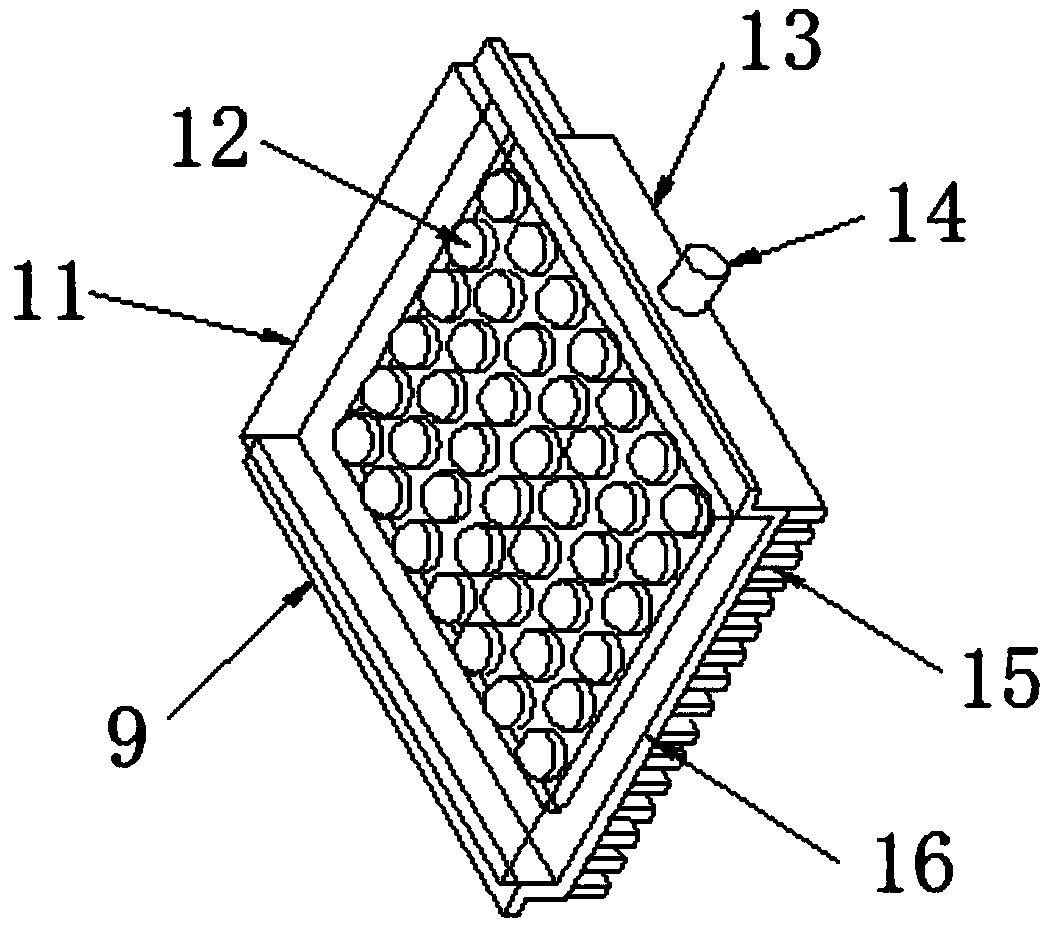
[0025] An energy-saving and environment-friendly LED floodlight, comprising a base 1, a bracket 2, and a floodlight 9 installed on the bracket 2, the bracket 2 is provided with a chute 3 along the vertical direction, and the chute 3 is located The front end is provided with an "N"-shaped piece 8, and the "N"-shaped piece 8 is connected to the bracket 2 through an adjusting bolt 4, and the upper end of the "N"-shaped piece 8 is connected with a "匚" by a screw. Type 10, the floodlight 9 is sandwiched in the middle of the "匚" type 10, the floodlight 9 is composed of an aluminum substrate 16, an LED lamp bead 12 installed on the upper surface of the aluminum substrate 16, and a The side plates 13 on both sides of the aluminum base plate 16 are composed of rotating shafts 14 installed on the sides of the side plates 13, and the floodlight 9 is rotatably connected with the "匚" type piece 10 through the ...

Embodiment 2

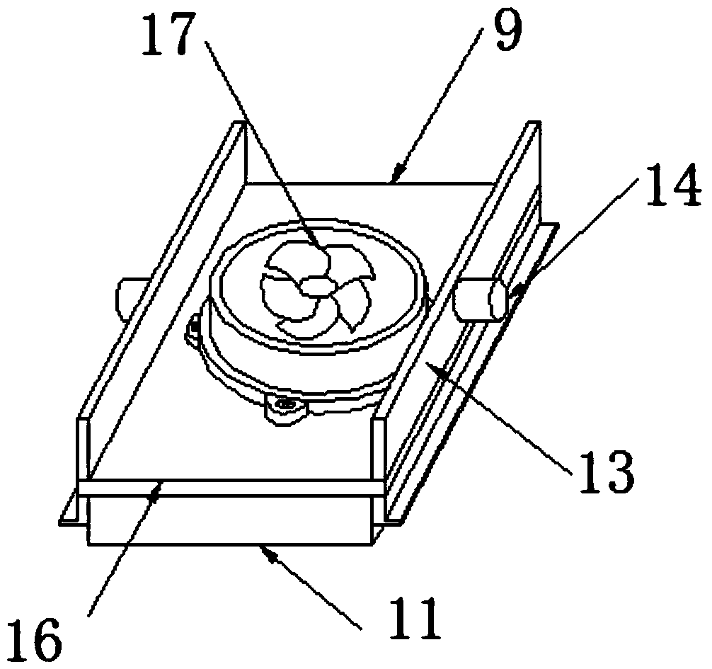
[0032] see image 3 , the present invention provides a technical solution: the difference from Embodiment 1 is that the heat dissipation structure is a heat dissipation fan 17, and the four ends of the heat dissipation fan 17 are fixed on the bottom of the aluminum substrate 16 by screws, and the heat dissipation fan 17 17 speeds up the air circulation, dissipates the heat in time, and improves the effect of heat dissipation. At the same time, the cooling fan 17 can be driven by power supply 6 .


PUM


Abstract

The invention discloses an energy-saving environment-friendly LED projection lamp. The energy-saving environment-friendly LED projection lamp comprises a base, a support and a projection lamp body arranged on the support; a sliding groove is formed in the support in the vertical direction, an N-shaped part is arranged at the front end of the sliding groove, a [-shaped part is connected to the upper end of the N-shaped part through a screw, the projection lamp body is clamped in the middle of the [-shaped part, the projection lamp body is composed of an aluminum substrate, LED lamp beads arranged on the upper surface of the aluminum substrate and side plates on the two sides of the aluminum substrate, rotating shafts are arranged on the side faces of the side plates, the projection lamp body is rotatably connected with the [-shaped part through the rotating shafts, a cooling cavity is formed between the side plates on the two sides of the aluminum substrate, a cooling structure is arranged in the cooling cavity, through adjusting the looseness degree of adjusting bolts, the projection lamp body can slide up and down along the sliding groove in the support, the aim of adjusting theheight of the projection lamp is achieved, the projection lamp body can do angle adjustment on the [-shaped part, and the irradiation effect of the projection lamp can be improved.

Description

technical field [0001] The invention relates to the technical field of floodlights, in particular to an energy-saving and environment-friendly LED floodlight. Background technique [0002] Flood light, which makes the illuminance on the designated illuminated surface higher than that of the surrounding environment. Also known as floodlights. Generally, it is capable of aiming in any direction and has a structure that is not affected by climatic conditions. It is mainly used for large-area operation sites, mines, building outlines, stadiums, overpasses, monuments, parks and flower beds, etc. Therefore, almost all large-area lighting fixtures used outdoors can be regarded as floodlights. The angle of the outgoing beam of the floodlight is wide or narrow, and the range of change is between 0° and 180°. Among them, the beam with a particularly narrow beam is called a searchlight. [0003] Generally, it is capable of aiming in any direction and has a structure that is not aff...

Claims


Application Information

Patent Timeline
Patent Type & Authority Applications(China)
IPC IPC(8): F21S8/08F21V21/34F21V19/02F21V29/76F21V15/01F21V21/00F21V23/00F21V23/04F21V29/67F21Y115/10
CPCF21S8/08F21V15/01F21V19/02F21V21/00F21V21/34F21V23/02F21V23/04F21V29/67F21V29/76F21Y2115/10
Inventor 梅霖
Owner WUHU CHUNYUAN PHOTOELECTRIC EQUIP TECH CO LTD
Why Eureka
Try Eureka