An ashes storage rack for ancestral halls with dustproof function
A storage rack and functional technology, applied in the field of ashes storage racks, can solve the problems of weak structure, poor sealing, inconvenient maintenance, etc., and achieve the effect of convenient visit
- Summary
- Abstract
- Description
- Claims
- Application Information
AI Technical Summary
Problems solved by technology
Method used
Image
Examples
Embodiment 1
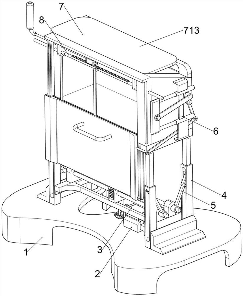
[0088] A ancestral hall with dustproof function ashes storage rack, such as figure 1 As shown, it includes a base 1, a fixed seat 2, a servo motor 3, a placement mechanism 4 and a dust-proof mechanism 7, the top of the base 1 is provided with a fixed seat 2, the fixed seat 2 is provided with a servo motor 3, and the top of the base 1 is provided with The placement mechanism 4 is provided with a dust-proof mechanism 7 on the placement mechanism 4 .
[0089] The user places the urn or memorial tablet in the placement mechanism 4, and then swings the dustproof mechanism 7 upwards to prevent dust. When the storage rack needs to be cleaned, the dustproof mechanism 7 can be swung downwards, Take out the tablet and clean it and the inside of the storage rack.
Embodiment 2
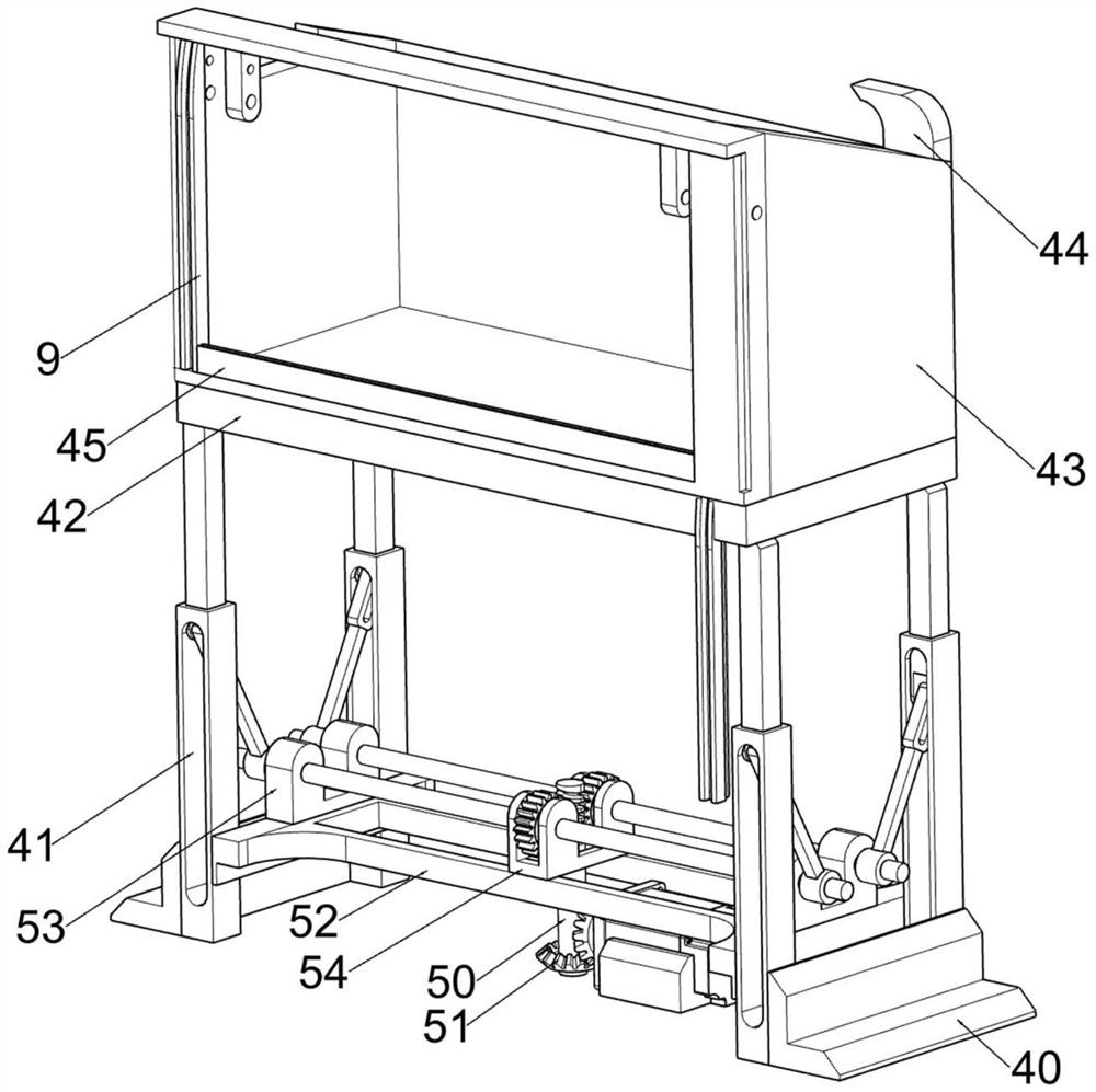
[0091] On the basis of Example 1, such as figure 1 , figure 2 and Figure 6 As shown, the placement mechanism 4 includes a reinforcement block 40, a first support block 41, a placement platform 42, a placement basket 43, a second support block 44 and a limit plate 45, and the top of the base 1 is symmetrically provided with the reinforcement block 40, and the base 1 The top is provided with four first support blocks 41, a placement platform 42 is placed between the tops of the first support blocks 41, a placement basket 43 is provided on the top of the placement platform 42, and a second support block 44 is provided on the right rear side of the top of the placement basket 43. A limiting plate 45 is provided on the front side of the top of the placing platform 42 .
[0092] The dustproof mechanism 7 includes the seventh connecting plate 70, the rotating ring 71, the sixth connecting rod 72, the spring 73, the second rotating rod 74, the eighth connecting plate 75, the third...
Embodiment 3
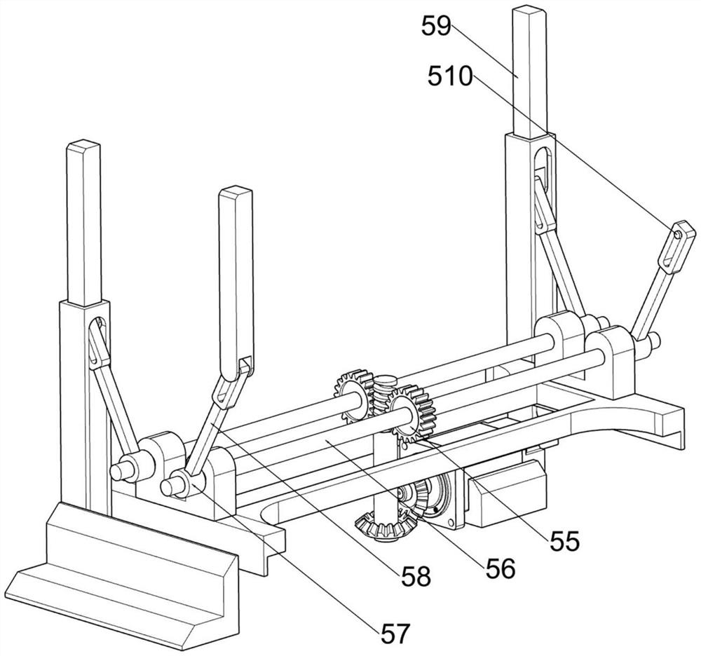
[0095] On the basis of Example 2, such as Figure 2-5 and Figure 7-8 Shown, also comprise lifting mechanism 5, and lifting mechanism 5 comprises worm screw 50, bevel gear 51, first connecting plate 52, the 3rd supporting block 53, the first connecting block 54, worm wheel 55, first rotating rod 56, rotating Block 57, the second connecting plate 58, the second connecting block 59 and the first connecting rod 510, the base 1 top middle part is rotatably provided with a worm screw 50, the bottom of the worm screw 50 and the output shaft of the servo motor 3 are all provided with a bevel gear 51, two The bevel gears 51 are meshed, the first connecting plate 52 is arranged between the lower parts of the first supporting block 41, the third supporting block 53 is arranged symmetrically on the top of the first connecting plate 52, and the first connecting block is arranged in the middle of the first connecting plate 52 54, the third supporting block 53 is provided with two first ro...
PUM
 Abstract
Description
Claims
Application Information
 - R&D
- Intellectual Property
- Life Sciences
- Materials
- Tech Scout
- Unparalleled Data Quality
- Higher Quality Content
- 60% Fewer Hallucinations
Browse by: Latest US Patents, China's latest patents, Technical Efficacy Thesaurus, Application Domain, Technology Topic, Popular Technical Reports.
© 2025 PatSnap. All rights reserved.Legal|Privacy policy|Modern Slavery Act Transparency Statement|Sitemap|About US| Contact US: help@patsnap.com


