
A rotary device for automatic silk laying equipment

A rotary device and automatic wire laying technology, applied in the field of rotary devices, can solve the problems of low laying operation efficiency, poor laying accuracy, and difficulty in processing fiber reinforced materials, and achieve high laying operation efficiency and stable laying quality. , The effect of laying high precision

Active Publication Date: 2020-04-14
BAODING BIAOZHENG MACHINE TOOL
View PDF13 Cites 0 Cited by
  • Summary
  • Abstract
  • Description
  • Claims
  • Application Information

AI Technical Summary

Problems solved by technology

However, the existing automatic wire laying equipment is widely used in the fields of aircraft, aerospace and military industry, and the technology is mainly controlled by European and American countries, which impose restrictions on the technology needs of our country; domestic technical personnel are also stepping up research, but only limited to some local technical improvements , such as the patent number 201210116290.8, the invention patent application titled the method and equipment for automatically laying prepreg filaments, which solved the technical problem that the prepreg filaments could not be compacted due to the lifting of the pressure roller when it encounters hemming; the patent number is 201710032926 .X, the name is a kind of process equipment for fiber winding layup. In order to solve the problem that the existing fiber reinforced materials are difficult to process, a fixed outer ring, an inner disc that rotates freely in the outer ring, and a positioning in the inner disc are studied. A device consisting of a sleeve in a hole
However, due to the lack of cooperation with other technologies, it cannot be applied in practice, and whether it can be realized in practical applications is also a problem.
At present, there is not a complete automatic laying equipment for fiber composite materials in China, and foreign countries have been embargoing the import of such equipment to China, and have imposed a technical blockade. Therefore, the laying of fiber composite materials in China is manually processed and laid. Poor accuracy, slow speed, low laying efficiency, and unstable laying quality

Method used


Image

  • A rotary device for automatic silk laying equipment
  • A rotary device for automatic silk laying equipment

Examples


Embodiment Construction

[0011] The present invention will be further described below in conjunction with the accompanying drawings and specific embodiments.

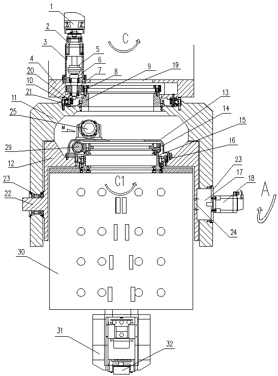
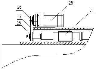
[0012] Such as figure 1 and figure 2 As shown, the present embodiment includes a fixed body 4, a C-axis rotary body 11, a C-axis rotary mechanism, a swing body 12, a C1-axis rotary mechanism, an A-axis rotary mechanism, and a control system. The inner ring 20 of the bearing 10 is fixed on the fixed ear A protruding from the lower end of the fixed body 4 , and its outer ring 21 is fixed on the fixed ear B protruded from the upper end of the C-axis rotating body 11 . The C-axis rotating mechanism fixed on the fixed body 4 drives the C-axis rotating body 11 to rotate along the central axis C of the C-axis rotating body. Further preferably, the C-axis turning mechanism includes a servo motor I 1 with a reducer I 2, an anti-backlash pinion gear set 7 with an anti-backlash mechanism, an anti-backlash bull gear 8 and a shaft coupling 5; the fixed ...


PUM


Abstract

The invention discloses a rotating device used for automatic wire laying equipment. The inner and outer rings of a bearing are fixed on a fixing lug A and a fixing lug B respectively, and a C-shaft rotating mechanism drives a C-shaft rotating body to rotate along a C shaft; the shaft, formed with a swinging body integrally, of two concentric shafts at the lower end part of the swinging body is hinged to one mounting hole B formed in a C-shaft rotating body, and the other shaft of the two concentric shafts is the output shaft of an A-shaft rotating mechanism; the A-shaft rotating mechanism is fixed in the other mounting hole B formed in the C-shaft rotating body and drives the swinging body to rotate along the A shaft; a C1-shaft rotating mechanism drives a yarn frame to rotate along the C1shaft; a braking device is mounted on the swinging body; and a controlling system controls the operation of the C shaft, the C1 shaft, the A-shaft rotating mechanism and the braking device. By meansof the automatic wire laying equipment with the rotating device, besides that moving of X, Y and Z shafts can be achieved, the rotating of the C shaft, the C1 shaft, the A-shaft can also be achieved,the fact that a wire laying head rotates at any angle in a space can be achieved, the laying precision is high, the speed is high, and the laying operation efficiency is high.

Description

technical field [0001] The invention relates to a rotary device of automatic fiber laying equipment used for laying fiber composite materials. Background technique [0002] Fiber composites are widely used in industries such as aircraft, aerospace, wind power and transportation. The current processing methods of fiber-reinforced composites are mainly hand lay-up, vacuum bag, molding and automatic silk laying process. Automatic wire laying technology is a key development technology in the fields of aircraft, aerospace, wind power and transportation in the future. However, the existing automatic wire laying equipment is widely used in the fields of aircraft, aerospace and military industry, and the technology is mainly controlled by European and American countries, which impose restrictions on the technology needs of our country; domestic technical personnel are also stepping up research, but only limited to some local technical improvements , such as the patent number 20121...

Claims


Application Information

Patent Timeline
Patent Type & Authority Patents(China)
IPC IPC(8): B29C70/38
CPCB29C70/382
Inventor 邝连杰支勉
Owner BAODING BIAOZHENG MACHINE TOOL
Learn More