
Mobile phone supporting device

A technology for a support device and a mobile phone, which is applied in the direction of the structure of the phone, can solve the problems of no bracket, can not be fixed, damaged, etc., and achieve the effects of good market prospects, simple structure, and easy implementation.

Active Publication Date: 2018-10-19
深圳市智高翔科技发展有限公司
View PDF13 Cites 0 Cited by
  • Summary
  • Abstract
  • Description
  • Claims
  • Application Information

AI Technical Summary

Problems solved by technology

However, although this ring part can be turned over at multiple angles, it can only be exposed on the back of the mobile phone, causing the mobile phone to be unable to be placed flat, and it needs to take up a large space, especially when the mobile phone is placed together with other items. It is very easy to cause damage to other items, thereby causing unnecessary losses
In addition, this kind of ring parts only have the function of socketing fingers, and do not have the function of a bracket, and cannot be fixed in the corresponding position, which is difficult to meet the market demand

Method used


Image

  • Mobile phone supporting device
  • Mobile phone supporting device
  • Mobile phone supporting device

Examples


Embodiment 1

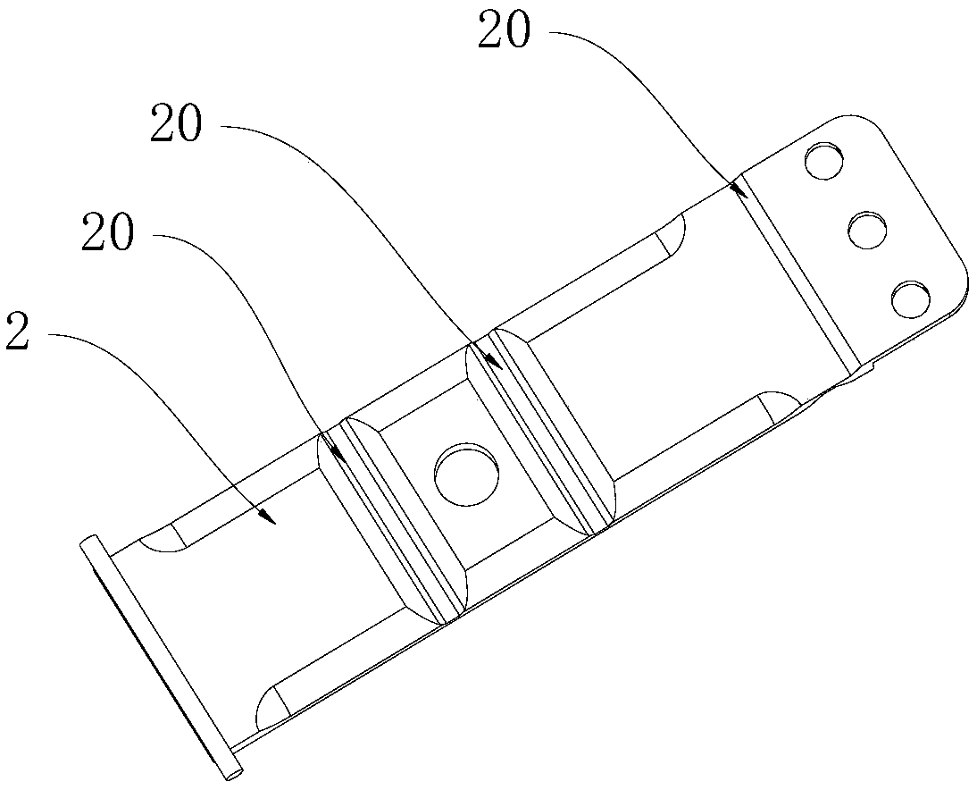
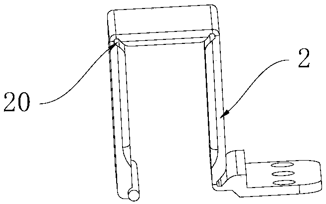
[0034] This embodiment proposes a mobile phone supporting device, combined with Figure 1 to Figure 8 As shown, it includes a fixed part 1 and a movable part 2, the fixed part 1 is used for fixed connection with the mobile phone, the first end of the movable part 2 is fixedly connected with the fixed part 1, the movable part 2 The second end is slidably connected to the fixed part 1, and the second end of the movable part 2 can slide back and forth along the length direction of the movable part 2, and at least three bending parts 20 are formed on the movable part 2, When the second end of the movable part 2 slides toward the first end, the movable part 2 bulges upwards, so that a locking hole 21 is formed between the movable part 2 and the fixed part 1, and when the movable part 2 When the second end of the part 2 slides away from the first end, the movable part 2 is attached to the fixed part 1 .

[0035] In the above mobile phone supporting device, three or more bending par...

Embodiment 2

[0041] to combine Figure 9 and Figure 10 As shown, the difference between this embodiment and Embodiment 1 is that a first magnet 31 is fixed in the insertion hole 30, a second magnet 23 is fixed on the outside of the movable part 2, and the second magnet 23 and The first magnets 31 are aligned and the two are magnetically attracted to each other.

Embodiment 3

[0043] to combine Figure 11 and Figure 12 As shown, as an alternative, in this embodiment, a vacuum suction cup 32 is fixed inside the jack 30, the outer surface of the movable part 2 is a smooth plane, and the vacuum suction cup 32 is adsorbed on the movable part 2 of the outer surface.


PUM


Abstract

The invention discloses a mobile phone supporting device, comprising a fixing member and a moving member, wherein the fixing member is fixedly connected with a mobile phone, the first end of the moving member is fixedly connected with the fixing member, the second end of the moving member is slidably connected to the fixing member, and the second end of the moving member can perform reciprocatingsliding along the length direction of the moving member, at least 3 bending parts are formed on the moving member, when the second end of the moving member slides towards the direction of the first end, the moving member is raised upwards to ensure that a clamping hole is formed between the moving member and the fixing member, and when the second end of the moving member slides towards the direction away from the first end, the moving member is attached to the fixing member. The mobile phone supporting device disclosed by the invention can be unfolded and folded, is helpful for holding the mobile phone, is convenient to lay the mobile phone, saves space, can avoid damaging other items, and also has the advantages of simple structure and low cost.

Description

technical field [0001] The invention relates to mobile phone accessories, in particular to a mobile phone supporting device. Background technique [0002] In the prior art, in order to meet the needs of visual effects and display effects, many mobile phones are designed with larger screen sizes. For the convenience of holding such large-screen mobile phones, some users usually paste a ring part on the back of the mobile phone. Put your finger through the ring to prevent your phone from falling. However, although this ring part can be turned over at multiple angles, it can only be exposed on the back side of the mobile phone, causing the mobile phone to be unable to be placed flat, and it needs to take up a large space, especially when the mobile phone is placed together with other items. It is very easy to cause damage to other items, thereby causing unnecessary losses. In addition, this type of ring component only has the function of socketing fingers, but does not have t...

Claims


Application Information

Patent Timeline
Patent Type & Authority Applications(China)
IPC IPC(8): H04M1/04
CPCH04M1/04Y02A30/00
Inventor 朱长仙
Owner 深圳市智高翔科技发展有限公司
Learn More