A smart home monitoring device

A monitoring device and smart home technology, which is applied in control/adjustment system, position/direction control, non-electric variable control, etc. It can solve the problems that the camera cannot meet the monitoring work, the camera cannot adjust the angle, and it is inconvenient to maintain. It is easy to disassemble , high practicability, and convenient maintenance

Active Publication Date: 2020-10-09
YANTAI SANXIN NEW ENERGY TECH CO LTD
View PDF6 Cites 0 Cited by
  • Summary
  • Abstract
  • Description
  • Claims
  • Application Information

AI Technical Summary

Problems solved by technology

[0003] After retrieval, the authorized announcement number is a smart home monitoring device disclosed by CN207068205U, which includes a body, the upper end of which is threaded to a base, and several bolt holes are opened inside the base, and the body A bracket is fixedly connected to the center of the lower end surface, a groove is opened on the lower surface of the bracket, a probe is installed inside the groove, a drive motor is installed at the center position inside the body, and the drive motor passes through the rotating shaft Rotationally connected with the probe, the surface of the probe is equipped with a ring of photosensitive sensors, and the outer surface of the bracket is provided with several through holes, the through holes communicate with the inside of the body, but the camera cannot perform vertical orientation. The angle adjustment of the camera can not meet a wider range of monitoring work, and the camera is fixed, which makes it difficult to maintain when the camera fails. Therefore, we propose a smart home monitoring device to solve the above problems

Method used


Image

  • A smart home monitoring device
  • A smart home monitoring device
  • A smart home monitoring device

Examples


Embodiment

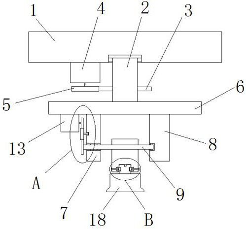
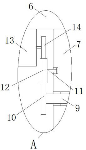
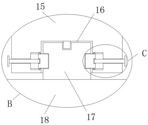
[0024] reference Figure 1-5 In this embodiment, a smart home monitoring device is proposed, which includes a mounting base 1, a first support column 2 is rotatably mounted on the bottom of the mounting base 1, and a first gear 3 is fixedly sleeved on the outer side of the first support column 2. One side of a support column 2 is provided with a first motor 4 fixedly installed at the bottom of the mounting base 1. The output shaft of the first motor 4 is fixedly sleeved with a second gear 5 meshing with the first gear 3. The first support The bottom end of the column 2 is fixedly mounted with a support base 6, and the bottom of the support base 6 is fixedly mounted with a first support plate 7 and a second support plate 8. The first support plate 7 and the second support plate 8 are rotatably mounted with the same The second support column 9, the end of the second support column 9 away from the second support plate 8 penetrates the first support plate 7 and is fixedly sleeved w...


PUM


Abstract

The invention discloses a smart home monitoring device, which comprises a mounting base, a first supporting column is installed on the bottom of the mounting base in rotation, a first gear is provided on the outer side of the first supporting column, and one side of the first supporting column There is a first motor fixedly installed at the bottom of the mounting seat, a second gear meshing with the first gear is fixedly sleeved on the output shaft of the first motor, a support seat is fixedly installed on the bottom end of the first support column, and the support seat A first support plate and a second support plate are fixedly installed at the bottom of the base, and the same second support column is rotatably installed between the first support plate and the second support plate. The present invention has high practicability, and the monitoring orientation of the camera body can be adjusted through the first motor and the second motor, thereby expanding the monitoring range of the camera body, and the camera body is easy to disassemble, which facilitates the maintenance of the camera body.

Description

Technical field [0001] The invention relates to the technical field of smart homes, in particular to a smart home monitoring device. Background technique [0002] Smart home is a residential platform, using integrated wiring technology, network communication technology, security technology, automatic control technology, audio and video technology to integrate the facilities related to home life to build an efficient management system for residential facilities and family schedule affairs to improve Home safety, convenience, comfort, artistry, and to achieve an environmentally friendly and energy-saving living environment. [0003] After retrieval, the authorized announcement number is CN207068205U, a smart home monitoring device, including a main body, the upper end of the main body is screwed with a base, and a number of bolt holes are opened inside the base. A bracket is fixedly connected to the center of the lower end surface, the lower end surface of the bracket is provided wi...

Claims


Application Information

Patent Timeline
Patent Type & Authority Patents(China)
IPC IPC(8): H04N7/18F16M11/06G05D3/00
CPCH04N7/18F16M11/04F16M11/10F16M11/18H04N23/50
Inventor 徐琬茹
Owner YANTAI SANXIN NEW ENERGY TECH CO LTD
Why Eureka
Try Eureka