Luminescence keyboard

A light-emitting keyboard and light-emitting module technology, which is applied to legends, electrical components, electric switches, etc., can solve problems such as disturbing the user's vision

Inactive Publication Date: 2018-10-23
PRIMAX ELECTRONICS LTD
View PDF6 Cites 1 Cited by
  • Summary
  • Abstract
  • Description
  • Claims
  • Application Information

AI Technical Summary

Problems solved by technology

Through the above-mentioned structure, the keys 20 of the existing light-emitting keyboard 2 can emit light, however, the light beam B easily leaks from the perforation 261 of the frame plate 26, causing a halo around the key cap 201, which will interfere with the user's vision.

Method used


Image

  • Luminescence keyboard
  • Luminescence keyboard
  • Luminescence keyboard

Examples


Embodiment Construction

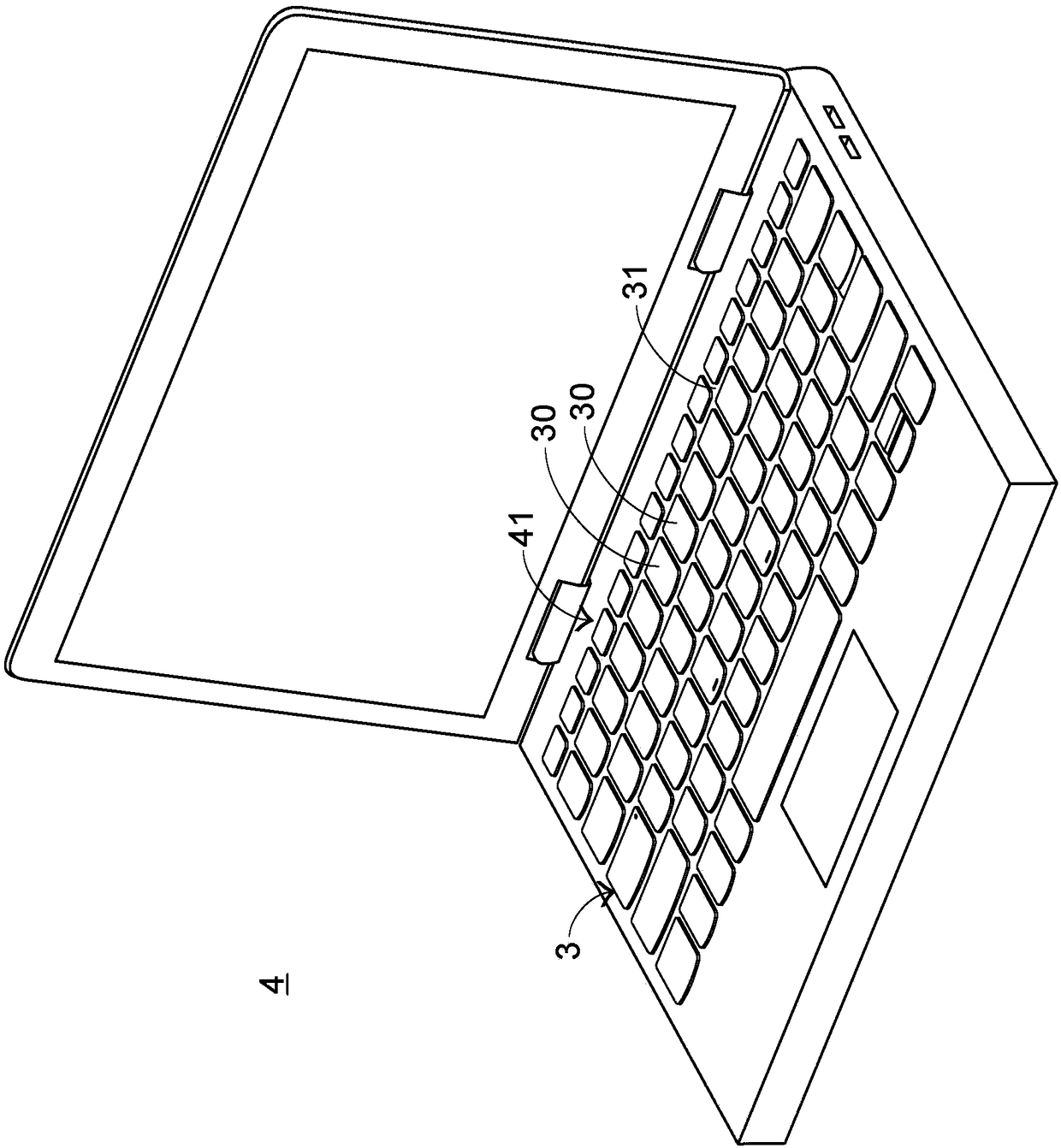
[0033] In view of the problems caused by the prior art, the present invention provides a luminous keyboard which can solve the problems of the prior art. See first image 3 , which is a schematic diagram of the appearance structure of the light-emitting keyboard and notebook computer in a preferred embodiment of the present invention. The luminous keyboard 3 of the present invention is disposed on the base 41 of the notebook computer 4 , and the luminous keyboard 3 includes a plurality of keys 30 and a frame 31 , and the plurality of keys 30 and the frame 31 are exposed outside the base 41 . The plurality of keys 30 can be pressed by the user's fingers to generate a corresponding signal, and the signal can be transmitted to the notebook computer 4, so that the notebook computer 4 can execute the function of the pressed key.

[0034] Next, the internal structure of the luminous keyboard 3 of the present invention will be described. Please also see Figure 4 as well as Figu...


PUM


Abstract

The invention discloses a luminescence keyboard. The luminescence keyboard comprises a luminescence module capable of generating a light beam, a key and a frame plate. The key has a key cap. The frameplate is located between the key and the luminescence module. A punching hole and an inclined plane wall are included. The key cap is inserted into the corresponding punching hole. Through arrangingthe inclined plane wall, the width of the upper portion end of the punching hole is less than the width of the lower portion end of the punching hole so that the inclined plane wall can partially cover the key cap and the light beam is prevented from leaking from the punching hole. By using the luminescence keyboard, a halation phenomenon can be improved.

Description

technical field [0001] The invention relates to an input device, in particular to a luminous keyboard with a luminous function. Background technique [0002] Common computer peripheral input devices include a mouse, a keyboard, and a trackball. The keyboard can directly input text and symbols to the computer, so it is highly valued by users and input device manufacturers. The subject of this case is the keyboard. [0003] see figure 1 , which is a schematic diagram of an appearance structure of an existing keyboard. There are a plurality of keys 10 on the surface of the existing keyboard 1, and the plurality of keys 10 are classified into general keys 101, number keys 102, and function keys 103. The corresponding signal is given to the computer to make the computer perform the pressed key function. For example, the general key 101 is used to input symbols such as English letters, the number key 102 is used to input numbers, and the function key 103 is used to provide vari...

Claims


Application Information

Patent Timeline
Patent Type & Authority Applications(China)
IPC IPC(8): H01H13/83
CPCH01H13/83H01H2219/064
Inventor 杨哲玮
Owner PRIMAX ELECTRONICS LTD
Why Eureka
Try Eureka