Airflow in aerosol generating system with mouthpiece

An aerosol generation and aerosol technology, which is applied in the fields of tobacco, food science, and tobacco processing, can solve problems such as unpleasantness of consumers, and achieve the effect of improving user experience.

Active Publication Date: 2018-10-23
PHILIP MORRIS PROD SA
View PDF27 Cites 3 Cited by
  • Summary
  • Abstract
  • Description
  • Claims
  • Application Information

AI Technical Summary

Problems solved by technology

When removing the mouthpiece to replace a used cartridge, consumers may experience an unpleasant sensation when gripping a wet cartridge

Method used


Image

  • Airflow in aerosol generating system with mouthpiece
  • Airflow in aerosol generating system with mouthpiece
  • Airflow in aerosol generating system with mouthpiece

Examples


Embodiment Construction

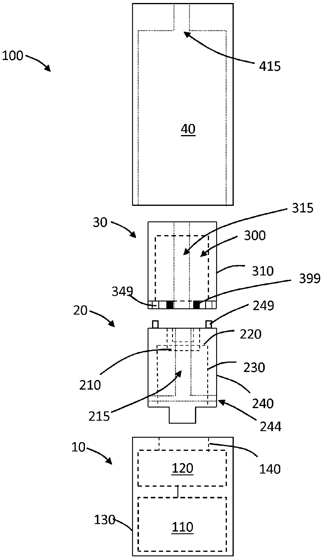
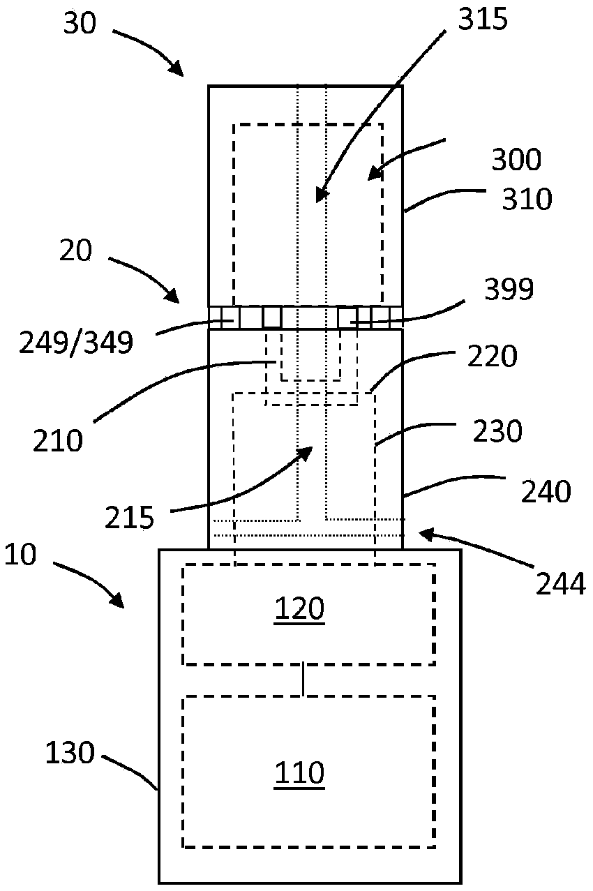
[0063] see now Figure 1A -C, the aerosol generating system 100 includes the first component 10 , the evaporation unit 20 , the enclosure 30 and the cover 40 . The first part 10 may be releasably connected to the evaporation unit 20 . The evaporation unit 20 may be releasably connected to the enclosure 30 . The hood 40 is placed over the evaporation unit 20 and the enclosure 30 . Cover 40 is releasably secured in place relative to evaporation unit 20 and enclosure 30 . In some examples (not depicted), components of the evaporation unit may be contained within the cartridge, and the system will not contain a separate evaporation unit.

[0064] The first component 10 comprises a housing 130 in which the power supply 110 and the electronic circuit 120 are housed. Electronic circuitry 120 is electrically coupled to power source 110 . Electrical conductors 140 may connect to contacts (not shown) exposed through, positioned on, or formed by housing 130 .

[0065] The evaporatio...


PUM


Abstract

An aerosol-generating system (100) has a mouth end (101) and a distal end (102). The system (100) includes a liquid storage portion that has a reservoir (300) containing an aerosol- generating substrate. The system (100) also includes a liquid transfer element (210) to which the aerosol-generating substrate from the reservoir (300) is transferable. The system (100) further includes a power supply(110) and a heating element (220) operably coupled to the power supply (110) and configured to heat the aerosol-generating substrate carried by the transport element (210) to form an aerosol. The system (100) also includes a cover (40) disposed over the liquid storage portion and includes one or more air flow channels (420) between the cover (40) and the liquid storage portion. The system (100) defines an aerosol flow path that extends at least from the liquid transport element (210) to the mouth end (101) of the system (100). In addition, the system (100) further defines an air flow path through the one or more channels (420) to the mouth end (101) of the system (100).

Description

technical field [0001] The present invention relates to an electrically heated aerosol generating system and associated devices, articles and methods. Background technique [0002] One type of aerosol generating system is an electrically operated elongated handheld aerosol generating system having a mouth end and a distal end. Known hand-held electrically operated aerosol generating systems may comprise a device portion including batteries and control electronics, a cartridge portion including a supply of aerosol generating substrate, and an electrically operated vaporizer. The vaporizer may comprise a coil of heating wire wrapped around an elongated core submerged in a liquid aerosol-generating matrix. Cartridges that include both a supply of aerosol-generating substrate and a vaporizer are sometimes referred to as "cartomizers." [0003] Cartridges comprising an aerosol-generating substrate typically contain a central passage through which the aerosol flows. When a user...

Claims


Application Information

Patent Timeline
Patent Type & Authority Applications(China)
IPC IPC(8): A24F47/00A24F40/10A24F40/485
CPCA24F40/10A24F40/485A24F40/42A24F40/46A24F40/57A24B15/167A24F47/00
Inventor E·福斯
Owner PHILIP MORRIS PROD SA
Why Eureka
Try Eureka