Prefabricated concrete bridge deck slab wet joint structure

A prefabricated concrete and prefabricated assembly technology, applied in the direction of bridges, bridge construction, bridge parts, etc., can solve the problems of slowing down the construction speed, unable to effectively prevent the generation and expansion of cracks, and increasing the construction cost. Improve force transfer performance and durability, prevent generation and expansion

Pending Publication Date: 2018-10-26
CHONGQING UNIV
View PDF0 Cites 6 Cited by
  • Summary
  • Abstract
  • Description
  • Claims
  • Application Information

AI Technical Summary

Problems solved by technology

Wet joint connection construction between prefabricated bridge decks cannot effectively prevent the generation and expansion of cracks
In addition, in order to ensure the strength of the commonly used wet joints with straight bar lap or welded s

Method used


Image

  • Prefabricated concrete bridge deck slab wet joint structure
  • Prefabricated concrete bridge deck slab wet joint structure
  • Prefabricated concrete bridge deck slab wet joint structure

Examples


Embodiment 1

[0025] This embodiment discloses a prefabricated concrete bridge deck wet joint structure, which includes a plurality of prefabricated concrete bridge decks 1 erected on longitudinal girders.

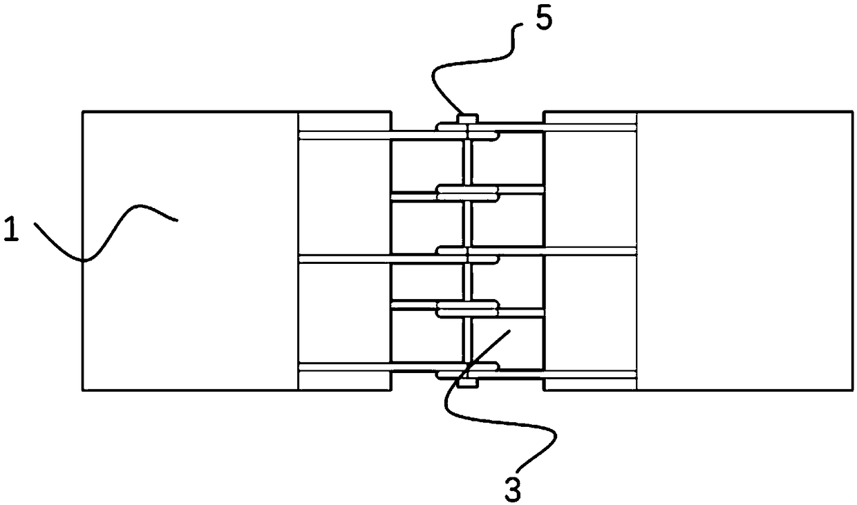
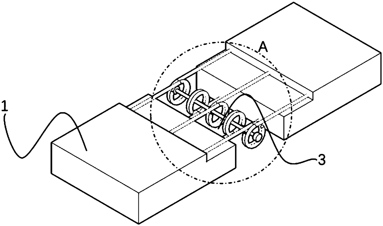
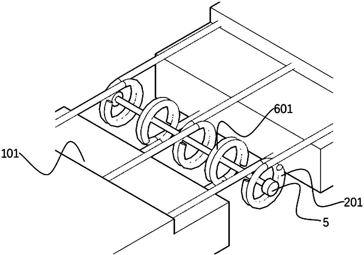
[0026] see figure 1 and figure 2 A wet joint 3 along the bridge direction is formed at intervals between two adjacent precast concrete bridge decks 1 . The precast concrete bridge deck 1 is a rectangular parallelepiped as a whole, and a rectangular parallelepiped is removed near the wet joint to form an alveolar 101 . A row of upper pre-embedded steel bars 2 are arranged at intervals along the bridge direction on the upper part of the precast concrete bridge deck 1 . The upper pre-embedded steel bar 2 protrudes from the tooth groove 101 near the wet joint side of the precast concrete bridge deck 1 . The end of the overhanging portion of the upper pre-embedded steel bar 2 is bent to form a single ring structure I201. A row of lower pre-embedded steel bars 6 are arranged at intervals...


PUM


Abstract

The invention provides a prefabricated concrete bridge deck slab wet joint structure. The wet joint structure comprises a plurality of prefabricated concrete bridge deck slabs erected on longitudinalbeams; a step-shaped wet joint in the direction along a bridge is formed between the every two adjacent prefabricated concrete bridge deck slabs in a spaced mode; and the sides, close to the wet joints, of the prefabricated concrete bridge deck slabs are provided with upper-layer pre-embedded steel bars and lower-layer pre-embedded steel bars which all extend to the outer sides of the prefabricated concrete bridge deck slabs; engineered cementitious composites (ECC) concrete is poured into the wet joints in a cast-in-place mode; and the every two adjacent prefabricated concrete bridge deck slabs are connected into a whole through adjacent ECC concrete. According to the wet joint structure, the ability of transmitting shear force and bending moment of the wet joints is improved, and generating and expansion of cracks at the wet joints can be effectively prevented.

Description

technical field [0001] The invention relates to the technical field of bridge structures, in particular to a bridge deck wet joint structure. Background technique [0002] Due to the early construction of many bridges in our country, these bridges are gradually aging and reaching their service life, and many bridges need to be repaired or even replaced. When repairing or replacing bridges, full consideration must be given to blocking traffic, and the time for repairing or replacing bridges must be shortened to a minimum. A fast, practical and economical way to replace the previous large-scale manual labor bridge construction method must be proposed. [0003] One of the most major problems with aging bridges is the deck. The deck is directly exposed to vehicular and pedestrian loads, adverse weather conditions, and corrosion from de-icing salts, so the deck degrades faster than the rest of the bridge. The traditional bridge deck construction method is to pour concrete on s...

Claims


Application Information

Patent Timeline
IPC IPC(8): E01D19/06
CPCE01D19/067Y02A30/30
Inventor 狄谨韩斌秦凤江尹志伟
Owner CHONGQING UNIV
Why Eureka
Try Eureka