Rear cover assembly of intelligent bearing storage gearbox

A gearbox and bearing technology, applied in the field of intelligent bearing storage gearbox rear cover assembly field, can solve the problems of poor willfulness, simple and rude installation of sealing rings, inability to achieve standardized operations, etc., and achieves a small footprint and compact structure. Effect

Active Publication Date: 2018-10-30
上善智城(苏州)信息科技有限公司
View PDF6 Cites 9 Cited by
  • Summary
  • Abstract
  • Description
  • Claims
  • Application Information

AI Technical Summary

Problems solved by technology

[0002] At present, the bearing cover of the main shaft of the gearbox is generally made of cast iron, which has poor willfulness. The existing assembly method generally uses a rubber hammer or a wooden hammer to manually knock the bearing into the bearing cover or bearing seat. The installation accuracy Difficult to control, unable to achieve standardized operations, simple and rough installation of sealing rings, prone to edge gnawing, how to provide an efficient, convenient, and easy-to-automatically controlled intelligent bearing storage gearbox rear cover assembly assembly and gearbox rear cover laser engraving assembly Technology has become a technical problem that needs to be solved urgently

Method used


Image

  • Rear cover assembly of intelligent bearing storage gearbox
  • Rear cover assembly of intelligent bearing storage gearbox
  • Rear cover assembly of intelligent bearing storage gearbox

Examples


Embodiment Construction

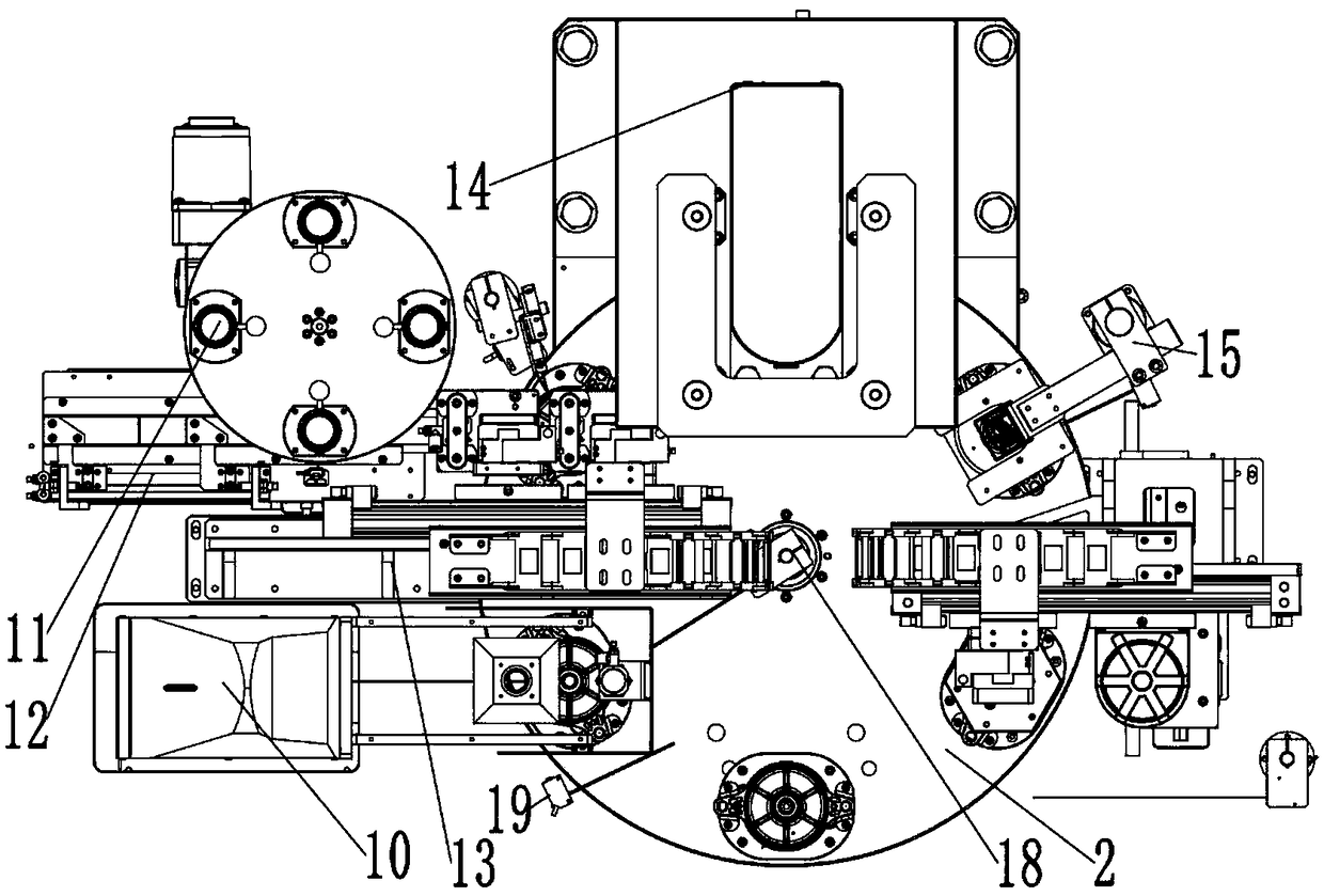
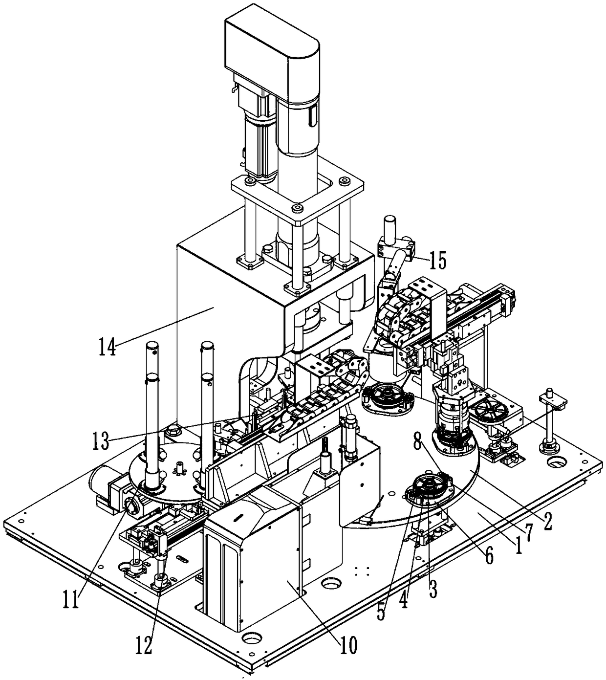
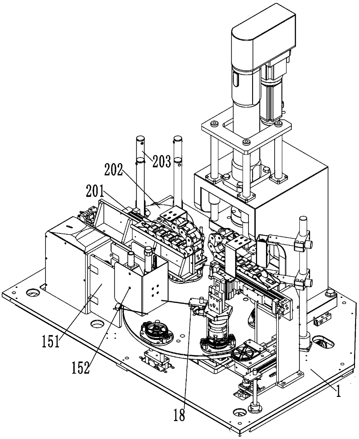
[0042] Such as Figure 1-10 As shown, the rear cover assembly assembly of the smart bearing storage gearbox of this embodiment includes a base 1, a rotating station device set on the base 1, a protective cover with an outer cover on the base 1, and a The assembly center of the gearbox rear cover corresponding to the rotating station device 2;

[0043] The rotary station device 2 includes a station drive motor 102 set on the base 1, a station drive motor 102 that is connected to the station drive motor 102 and rotates and is set on the base 1, and is distributed on the station drive plate 101 according to procedures. The rotating station, the mould part 6 arranged at each rotating station and used to fix the lower end surface of the gearbox cover 3, the U-shaped clamping seat 7 arranged on the symmetrical sides of the upper end surface of the mould part 6, and the setting The V-shaped positioning groove 8 on the U-shaped card seat 7 and used to fix the lugs on both sides of the g...


PUM


Abstract

The invention relates to a rear cover assembly of an intelligent bearing storage gearbox. The rear cover assembly comprises a base, a rotating station device arranged on the base, a protection cover externally covering the base, and a gearbox rear cover assembly center arranged on the base and corresponding to the rotating station device; the rotating station device comprises a station driving motor, a station rotating disc, rotating stations, mould parts, U-shaped clamping bases and V-shaped positioning grooves, wherein the station driving motor is arranged on the base, the station rotating disc is in transmission connection with the station driving motor and is rotationally arranged on the base, the rotating stations are distributed on the station rotating disc according to working procedures, the mould parts each are arranged at the corresponding rotating station and are used for fixing the lower end surface of a gearbox cover, the U-shaped clamping bases are arranged on the symmetric two sides of the upper end faces of the mould parts, and the V-shaped positioning grooves are formed in the U-shaped clamping bases and are used for fixing lugs on the two sides of the gearbox cover; and the rotating station device plays a role in working procedure transfer connection. The rear cover assembly is reasonable in design, compact in structure and convenient to use.

Description

Technical field [0001] The invention relates to a rear cover assembly assembly of an intelligent bearing storage gearbox. Background technique [0002] At present, the bearing cover of the gearbox spindle is generally made of cast iron, which is poor in willfulness. The existing assembly method generally uses a rubber hammer or wooden hammer to install the bearing into the bearing cover or bearing seat. The installation accuracy is It is not easy to control and can not achieve standardized operations. The installation of the sealing ring is simple and rough, and it is prone to gnawing. How to provide an efficient, convenient and automatic control of the intelligent bearing storage gearbox rear cover assembly and laser engraving assembly of the gearbox rear cover The process has become an urgent technical problem to be solved. Summary of the invention [0003] The technical problem to be solved by the present invention is generally to provide a smart bearing storage gearbox rear c...

Claims


Application Information

Patent Timeline
Patent Type & Authority Applications(China)
IPC IPC(8): B23K26/362B23K26/70B23P19/027
CPCB23K26/361B23K26/702B23P19/027
Inventor 周斯加黄智博赵云李峰平储军张毅
Owner 上善智城(苏州)信息科技有限公司
Why Eureka
Try Eureka