A piezoelectric generating floor

A piezoelectric power generation and floor technology, applied in the direction of generators/motors, piezoelectric effect/electrostrictive or magnetostrictive motors, electrical components, etc., to achieve the effects of reasonable structure, sufficient electric energy, and high power generation efficiency

Inactive Publication Date: 2019-07-12
BEIJING UNIV OF TECH
View PDF7 Cites 0 Cited by
  • Summary
  • Abstract
  • Description
  • Claims
  • Application Information

AI Technical Summary

Problems solved by technology

[0005] The present invention will collect the energy generated by the walking pressure of the human body on the floor, use the positive piezoelectric effect to generate electricity, and store the electric energy in the energy storage structure to solve the energy supply problem of the smart home system or the miniature electronic equipment in public places

Method used


Image

  • A piezoelectric generating floor
  • A piezoelectric generating floor
  • A piezoelectric generating floor

Examples


Embodiment Construction

[0032] The present invention will be described in further detail below in conjunction with specific embodiments.

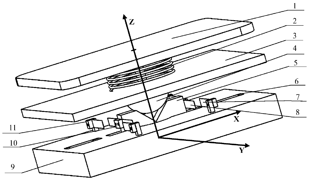
[0033] Such as Figure 1 to Figure 10 Shown, a new type of piezoelectric power generation floor.

[0034] figure 1 It is a schematic diagram of the overall structure assembly, divided into two parts: the upper lift part and the lower power generation part.

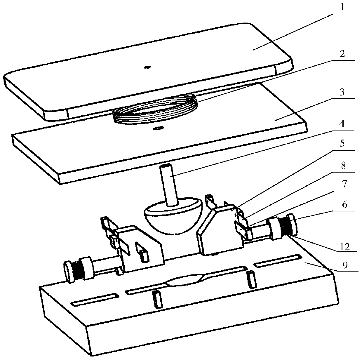
[0035] Such as figure 2 As shown, figure 2 This is an exploded view of the overall structure. The overall structure includes an upper cover plate 1, a lifting spring 2, a middle positioning plate 3, a hemispherical pressure rod 4, two symmetrically installed moving sliders 5, and four moving piezoelectric cantilevers Beam 8, four fixed piezoelectric cantilever beams 7, two movable piezoelectric cantilever beam clamps 10, four fixed piezoelectric cantilever beam clamps 11, two pressure springs 12, two piezoelectric sheets 6, two push rod rubbers Ring 13 and a lower substrate 9.

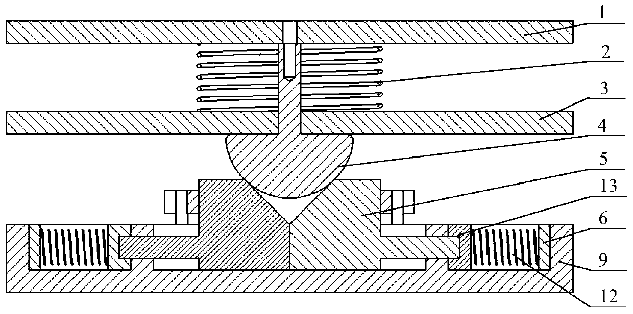
[0036] Such as image 3 with Figur...


PUM


Abstract

The invention relates to a piezoelectric power generating floor, which comprises an upper-layer lifting part and a lower-layer power generating part, wherein the upper-layer lifting part comprises anupper-layer cover plate, a lifting spring, a hemispherical pressure rod and a middle-layer positioning plate, and the lower-layer power generating part comprises moving sliding blocks, fixed piezoelectric cantilever beams, moving piezoelectric cantilever beams, a lower-layer substrate, pressure springs and piezoelectric pieces. Pressure is applied to the moving sliding blocks by the hemisphericalpressure rog, and electric energy is generated by movement of the moving piezoelectric cantilever beams mounted on the moving sliding blocks and impact of the tail ends of the fixed piezoelectric cantilever beams fixed on the lower-layer substrate. In addition, each pressure spring at one end of the corresponding moving sliding block is squeezed to apply pressure to the piezoelectric pieces to generate electric energy. When the pressure is released, the upper-layer cover plate of the floor ascends when the pressure, the moving sliding blocks move towards opposite directions under the action ofrestoring forces of the pressure springs at the end parts and the tail ends of the piezoelectric cantilever beams impact again to generate electric energy. The piezoelectric power generating floor isapplied to energy supply of smart home or electric energy collection of public places with relatively high human traffic.

Description

Technical field [0001] The invention relates to a method and a device for collecting electric energy by using the positive piezoelectric piezoelectric effect and realizing the collection of energy generated by stepping on the ground when the human body is walking, which can effectively convert the walking pressure of the human body loaded on the floor into electric energy, belonging to piezoelectric energy collection And the field of power generation floor design. Background technique [0002] In recent years, with the deepening of research on piezoelectric materials, the collection of vibration energy has gradually become popular. The collection of vibration energy has the advantages of environmental protection and low cost. The positive piezoelectric effect of piezoelectric materials can convert the vibration energy of moving parts into electrical energy. , And can realize the energy supply of other micro electronic equipments by laying the floor on the ground, which is a feasi...

Claims


Application Information

Patent Timeline
Patent Type & Authority Patents(China)
IPC IPC(8): H02N2/18E04F15/02
CPCE04F15/02E04F2290/00H02N2/18H02N2/186
Inventor 姚明辉彭乐伦景浩马立
Owner BEIJING UNIV OF TECH
Why Eureka
Try Eureka