Novel commutation switch device

A phase change switch, a new type of technology, applied in the direction of reducing the asymmetry of the multi-phase network, eliminating/reducing the asymmetry of the multi-phase network, etc., to achieve the effect of zero switching time and ensuring the continuity of power supply

Pending Publication Date: 2018-11-02
北京智创骏驰电气科技有限公司
View PDF6 Cites 7 Cited by
  • Summary
  • Abstract
  • Description
  • Claims
  • Application Information

AI Technical Summary

Problems solved by technology

[0005] Aiming at the problem that the current commutation switch type three-phase load unbalance control device inevitably exists in the commutation process, the commutation time may affect the continuity of the user's electricity consumption. This invention proposes a new phase commutation switch device, which not only ensures the The phase switch type three-phase load unbalance control device has the advantages of low loss, and avoids the time of commutation and power failure, which makes up for its own shortcomings.

Method used


Image

  • Novel commutation switch device
  • Novel commutation switch device
  • Novel commutation switch device

Examples


Embodiment Construction

[0037] In order to make the objects, technical solutions and advantages of the present invention more apparent, exemplary embodiments according to the present invention will be described in detail below with reference to the accompanying drawings. Apparently, the described embodiments are only some embodiments of the present invention, rather than all embodiments of the present invention, and it should be understood that the present invention is not limited by the exemplary embodiments described here. Based on the embodiments of the present invention described in the present invention, all other embodiments obtained by those skilled in the art without creative effort shall fall within the protection scope of the present invention.

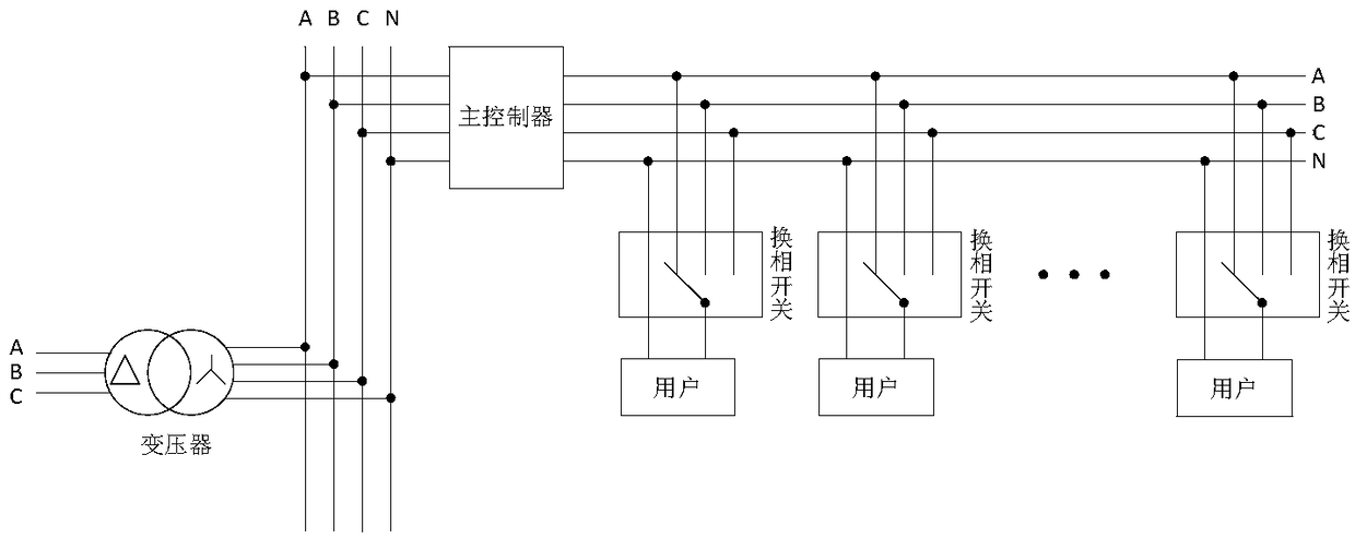
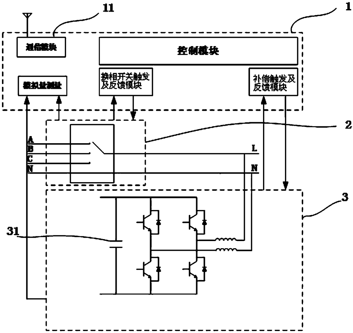
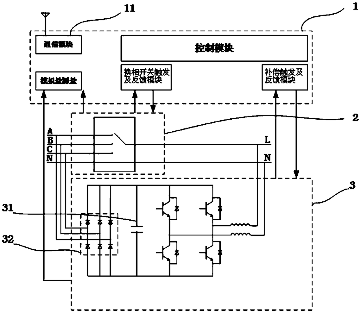
[0038] First, refer to Figure 2-Figure 4 A schematic principle diagram of a commutation switch device for realizing an embodiment of the present invention is described below.

[0039] like Figure 2-Figure 4 As shown, a new phase change switch d...


PUM


Abstract

The invention provides a novel commutation switch device. The device comprises a monitoring unit, a commutation switch unit and a compensation unit, wherein the monitoring control comprises a controlmodule, an analog quantity measurement module, a communication switch trigger and feedback module, a compensation trigger and feedback module and a communication module, the control module is used forreceiving a commutation command transmitted from the communication module and receiving a voltage/current signal acquired by the analog quantity measurement module, and information returned from morethan two modules is received by sending out a control command on the commutation switch unit and the compensation unit according to a certain control strategy. By the commutation switch device, the commutation time of a conventional commutation switch-type three-phase load unbalanced management device during the commutation process can be prevented, zero switching time can be achieved, and the power supply continuity is ensured.

Description

technical field [0001] This application relates to a new type of phase change switch device, which can be applied to the distribution station area to solve the unbalanced three-phase load problem in the station area. Background technique [0002] The distribution network is at the end of the power system, with long transmission distances, multiple step-down levels, and a wide range of points. The operation status is greatly affected by the operation mode and load changes. These conditions cause the distribution network to be in non-economic operation in a certain area and period of time. state, it is necessary to coordinate and control indicators such as voltage and reactive power. In the low-voltage three-phase four-wire power supply system, most of the power users are single-phase loads or mixed single-phase and three-phase loads, and the loads are different and the power consumption time is different, which leads to the three-phase load of the low-voltage power supply sys...

Claims


Application Information

Patent Timeline
Patent Type & Authority Applications(China)
IPC IPC(8): H02J3/26
CPCH02J3/26Y02E40/50
Inventor 任西周张雷冯波袁红光王福全屈雄飞何东霖
Owner 北京智创骏驰电气科技有限公司
Why Eureka
Try Eureka