Automatic garment conveying wardrobe rotating mechanism

A technology of rotating mechanism and wardrobe, applied in wardrobes, rotating cabinets, cabinets and other directions, can solve the problems of wasting time, inconvenient for users to take, increase the time for sorting clothes, etc., achieve simple installation and disassembly operations, and reduce the risk of falling off , Improve the effect of automatic clothing

Inactive Publication Date: 2018-11-06
佛山市艾温特智能科技有限公司
View PDF10 Cites 6 Cited by
  • Summary
  • Abstract
  • Description
  • Claims
  • Application Information

AI Technical Summary

Problems solved by technology

[0002] The current wardrobe is manually folded and placed by the user. Sometimes when the user is looking for clothes, he needs to rummage through the cabinets to find them, resulting in a waste of time. The clothes may be rearranged and folded again. When the user has many similar clothes When you want to find specific clothes, you need to spend more time and increase the time for sorting clothes. The emergence of automatic clothes-out wardrobes solves this problem, but the rotation mechanism of the automatic clothes-out wardrobe There is an inability to move the connecting rod on which specific clothes are hung to one side inside the closet, the efficiency of quickly finding specific clothes is low, and it is not convenient for users to take them

Method used


Image

  • Automatic garment conveying wardrobe rotating mechanism
  • Automatic garment conveying wardrobe rotating mechanism
  • Automatic garment conveying wardrobe rotating mechanism

Examples


Embodiment Construction

[0023] The following will clearly and completely describe the technical solutions in the embodiments of the present invention with reference to the accompanying drawings in the embodiments of the present invention. Obviously, the described embodiments are only some, not all, embodiments of the present invention. Based on the embodiments of the present invention, all other embodiments obtained by persons of ordinary skill in the art without making creative efforts belong to the protection scope of the present invention.

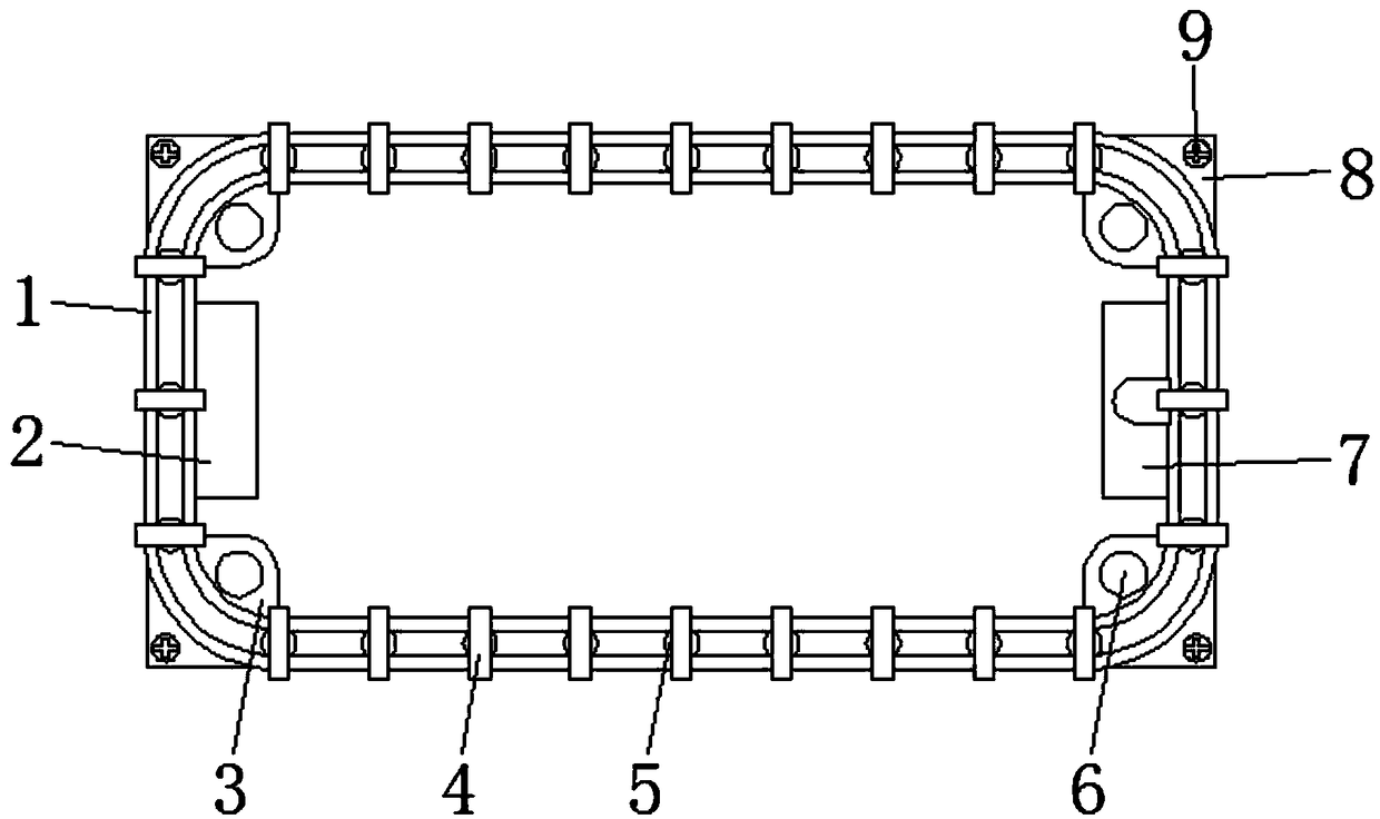
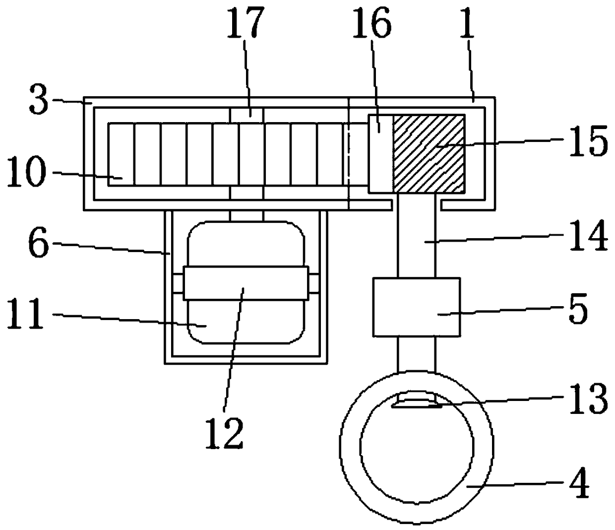
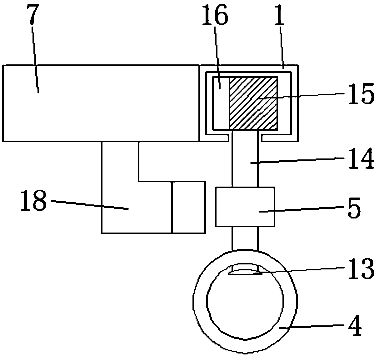
[0024] see Figure 1-4 , the present invention provides a technical solution: a wardrobe rotation mechanism for automatic unloading, including a chute 1, a rotating bin 3, an identifier 7, a motor 11, a connecting rod 14 and a belt 15, and the four corners of the chute 1 adopt a rounded shape Design, a belt 15 is movable inside the chute 1, and a rack 16 is provided on the outer wall of one side of the belt 15, the width of the belt 15 is greater than the widt...


PUM


Abstract

The invention discloses an automatic garment conveying wardrobe rotating mechanism. The mechanism comprises a sliding slot, rotating bins, an identifier, a motor, connecting rods and a belt. The sliding slot is internally movably provided with the belt, the outer wall of one side of the belt is provided with a rack, connecting rodsare fixed tothe lower surface of the belt,identification blocksarefixed tothe outer walls of the connecting rods, the rotating binsare fixed to four corners of the inner wall of the sliding slot, the rotating binsareinternally rotatably provided with gears, the lower surfaces of the rotating binsare fixed to motor protective covers, motorsare fixed inside the motor protective covers throughmotor holders, the identifier is mounted on an inner wall of one side ofthe sliding slot,an identifier probe is fixed tothe lower surface of the identifier, and a controller is fixed to the inner wall of one side of the sliding slot. According to themechanism, the identification blocks on the different connecting rods can be identified by setting the identifier to control the motor to stop rotating, the connecting rods withspecific clothes hanging are stopped on one side of the sliding slot, and the effect of providing convenience for people to take out is achieved.

Description

technical field [0001] The invention relates to the technical field of automatic clothes-out wardrobe equipment, in particular to a wardrobe rotation mechanism for automatic clothes-out. Background technique [0002] The current wardrobe is manually folded and placed by the user. Sometimes when the user is looking for clothes, he needs to rummage through the cabinets to find them, resulting in a waste of time. The clothes may be rearranged and folded again. When the user has many similar clothes When you want to find specific clothes, you need to spend more time and increase the time for sorting clothes. The emergence of automatic clothes-out wardrobes solves this problem, but the rotation mechanism of the automatic clothes-out wardrobe There is an inability to move the connecting rod on which specific clothes are hung to one side inside the wardrobe, and the efficiency of quickly finding specific clothes is low, which is inconvenient for users to take. Contents of the inv...

Claims


Application Information

Patent Timeline
Patent Type & Authority Applications(China)
IPC IPC(8): A47B61/00A47B49/00
CPCA47B49/008A47B61/00
Inventor 刘留李秉正
Owner 佛山市艾温特智能科技有限公司
Why Eureka
Try Eureka