Automatic reversing multistage reciprocating type hydraulic cylinder applied to agricultural machine

A technology of automatic reversing and agricultural machinery, applied in the direction of fluid pressure actuating devices, etc., can solve the problems of slow technological innovation of reciprocating cylinders, etc., achieve the effect of smooth and smooth state switching process, reduce working costs, and automate the reversing process

Inactive Publication Date: 2018-11-06
朱文祥
View PDF0 Cites 0 Cited by
  • Summary
  • Abstract
  • Description
  • Claims
  • Application Information

AI Technical Summary

Problems solved by technology

[0002] At present, industrial reciprocating cylinders are mainly used for pushing or pulling actions. Reciprocating cylinders are composed of hydraulic cylinders and air cylinders. Reciprocating cylinders are widely used in industrial systems due to their simple structure, low cost, and large force. However, due to the relatively simple long-term application requirements, The technological innovation of reciprocating cylinders is relatively slow; industrial manipulators require equipment with small size and flexible modes of movement, and generally cannot work under conditions of high load and high bearing capacity. Lift the brunt

Method used


Image

  • Automatic reversing multistage reciprocating type hydraulic cylinder applied to agricultural machine
  • Automatic reversing multistage reciprocating type hydraulic cylinder applied to agricultural machine
  • Automatic reversing multistage reciprocating type hydraulic cylinder applied to agricultural machine

Examples


Embodiment Construction

[0047] The technical solutions in the embodiments of the present invention will be clearly and completely described below in conjunction with the accompanying drawings in the embodiments of the present invention

[0048] It is obvious that the described embodiments are only a part of the embodiments of the present invention, but not all of them. Based on the embodiments of the present invention, all other embodiments obtained by persons of ordinary skill in the art without making creative efforts belong to the protection scope of the present invention.

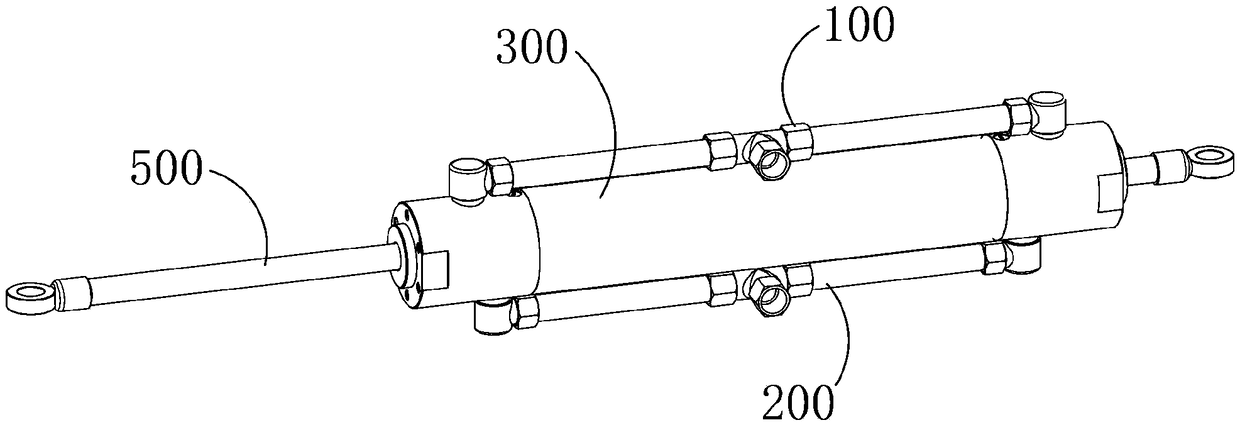
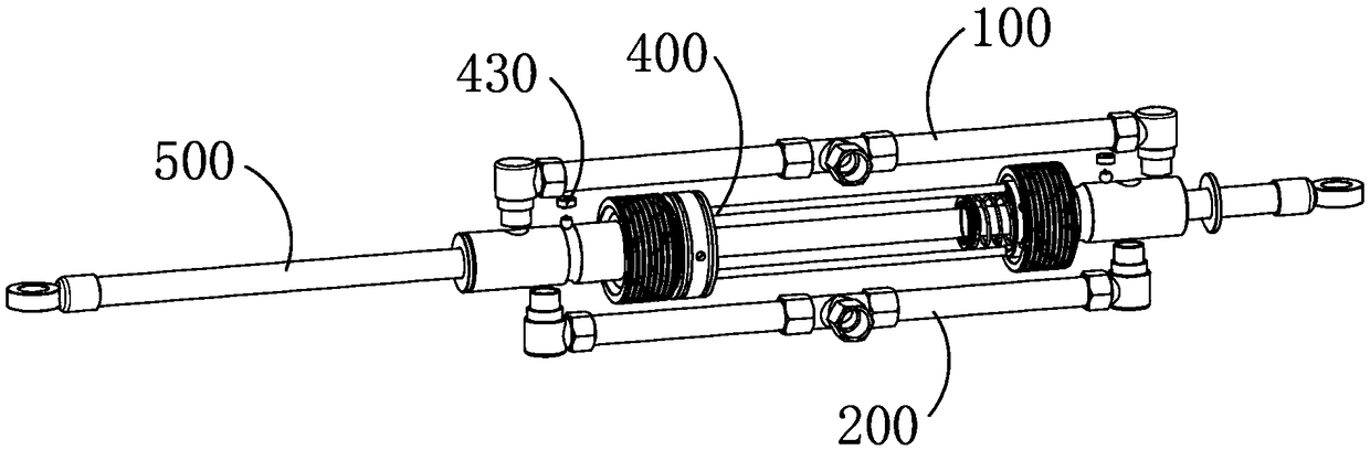
[0049] The present invention has the advantage of pulling the piston rod to reciprocate along its own axial direction through the reciprocating device, which is that the reciprocating device uses air as the power source and makes the piston pull the piston rod to move synchronously, which not only protects the environment and reduces energy consumption, but also reduces the working cost. At the same time, the piston moves and ...


PUM


Abstract

The invention provides an automatic reversing multistage reciprocating type hydraulic cylinder applied to an agricultural machine. The automatic reversing multistage reciprocating type hydraulic cylinder comprises an air inlet pipeline, an air discharging pipeline, a cylinder block, a reciprocating device and a piston rod, wherein the air inlet pipeline is matched with the air discharging pipelineand provides air for the reciprocating device; the reciprocating device is arranged in the cylinder block, takes air as a power source and pulls the piston rod to reciprocate along the axial direction of the piston rod; the reciprocating device comprises a reciprocating mechanism and a piston; the reciprocating mechanism comprises a reciprocating triggering component and a limited component; thelimited component is used for limiting the movement of the reciprocating triggering component; the reciprocating triggering component is used for receiving abutting force generated when the piston moves along the axial direction of a cylinder barrel, and completes state switching under the action of the abutting force; the reciprocating triggering component comprises a triggering column which is formed by two sections of cylinders which are coaxial, have different diameters and are respectively a sliding section and a circulating section.

Description

technical field [0001] The invention relates to an automatic reversing reciprocating cylinder. Background technique [0002] At present, industrial reciprocating cylinders are mainly used for pushing or pulling actions. Reciprocating cylinders are composed of hydraulic cylinders and air cylinders. Reciprocating cylinders are widely used in industrial systems due to their simple structure, low cost, and large force. However, due to the relatively simple long-term application requirements, The technological innovation of reciprocating cylinders is relatively slow; industrial manipulators require equipment with small size and flexible modes of movement, and generally cannot work under conditions of high load and high bearing capacity. Boost bears the brunt. Contents of the invention [0003] In order to solve the deficiencies of the prior art, the object of the present invention is to provide an automatic reversing reciprocating cylinder to solve the problems mentioned in th...

Claims


Application Information

Patent Timeline
Patent Type & Authority Applications(China)
IPC IPC(8): F15B15/14F15B15/20F15B15/24
CPCF15B15/14F15B15/20F15B15/24
Inventor 朱文祥
Owner 朱文祥
Why Eureka
Try Eureka