
Nozzle structure

一种结构体、喷嘴的技术,应用在铸造熔融物容器、制造工具、金属加工设备等方向,能够解决铸造时间延至很长时间等问题,达到容易卸下、抑制质量下降、高精度的效果

Active Publication Date: 2018-11-09
KROSAKI HARIMA CORP
View PDF8 Cites 2 Cited by
  • Summary
  • Abstract
  • Description
  • Claims
  • Application Information

AI Technical Summary

Problems solved by technology

However, in the continuous casting of steel, the casting time tends to be extended for a long time due to the multi-continuous casting etc., so that in order to replace a part of the nozzle such as the immersion nozzle, it is still necessary to replace a part of the nozzle by a plurality of The structure is composed of divided refractory parts, so there are still seams at this time

Method used


Image

  • Nozzle structure
  • Nozzle structure
  • Nozzle structure

Examples


Embodiment Construction

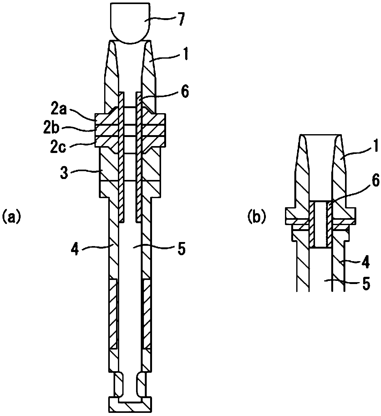
[0036] A typical form of the nozzle structure of the present invention with the largest number of divisions, that is, the number of joints, is an upper nozzle, a three-piece sliding nozzle plate (upper plate, middle plate, and lower plate), an intermediate nozzle, a lower nozzle, a dipping In the case of multiple refractory components such as nozzles. However, it is not necessary to be limited to this form, and the form which combined arbitrary 2 or more of each said refractory material may be sufficient. For example, figure 1 (a) is an example composed of upper nozzle 1, upper plate 2a, middle plate 2b, lower plate 2c, lower nozzle 3 and submerged nozzle 4, figure 1 (b) is an example constituted by the upper nozzle 1 and the submerged nozzle 4 . That is, the nozzle structure of the present invention is a nozzle structure for discharging molten steel provided with joints at one or more locations, the joints dividing and joining the molten steel discharge path having the in...


PUM


Abstract

The purpose of the present invention is to improve the sealing ability of a nozzle structure for discharging molten steel, which comprises a plurality of refractory members, and which has joint portions. This nozzle structure for discharging molten steel is provided with, at one or more locations, joint portions that each join vertically divided segments of a molten steel discharge path having aninner hole (5), wherein an inner hole sleeve (6) made of a refractory is disposed on the inner hole surface of the nozzle structure in such a manner as to straddle at least one of the joint portions in the vertical direction.

Description

technical field [0001] The present invention relates to a nozzle structure for discharging molten steel. Background technique [0002] For example, there are cases where a nozzle structure for discharging molten steel from a tundish and from its From the molten steel inlet to the casting mold, it is used as the molten steel discharge path. This is due to the fact that the flow rate control function in molten steel discharge is dynamically performed on a part of the nozzle structure, or the balance of durability is optimized against damage, etc., which is the molten steel discharge path. Different damages on each part of the body, or for partial replacement. [0003] In such a nozzle structure in which a plurality of refractory members are combined, a joint portion inevitably exists between the refractory members. On these joints, the joint material and sealing material cannot be used for the sliding part such as the sliding nozzle, so a so-called contact structure on the ...

Claims


Application Information

Patent Timeline
Patent Type & Authority Applications(China)
IPC IPC(8): B22D11/10B22D41/50
CPCB22D11/10B22D41/50B22D41/502B22D41/54
Inventor 福永新一黑田贵宏定野贤司冈田卓也溝部有人
Owner KROSAKI HARIMA CORP
Learn More