Pipe bending machine

A technology for pipe bending machines and pipe fittings, which is applied to metal processing equipment, feeding devices, positioning devices, etc., and can solve the problems of low bending efficiency of pipe bending machines

Pending Publication Date: 2018-11-13
张家港市越泰精密机械有限公司
View PDF0 Cites 12 Cited by
  • Summary
  • Abstract
  • Description
  • Claims
  • Application Information

AI Technical Summary

Problems solved by technology

[0005] The beneficial effect of the pipe bender of the present invention is that the feeder is used to send the linear pipe fittings to the clamping device, and the straight pipe fittings sequentially pass through the first space between the parallel bending wheels and the guide wheels, and between the positioning member and the guide wheels. One channel, finally inserted into the clamping tube of the clamping device, the guide wheel and the positioning piece are used to position the straight pipe, the bending wheel can move 90 degrees along the outer circumference of the guide wheel from the position parallel to the positioning piece through the drive of the rotating motor ° or 180°, the pipe is bent in the first plane; when the pipe needs to be bent in the second plane, the positioning part and the bending wheel slide outward, and the rotating motor controls the rotating arm and then drives the...

Method used


Image

  • Pipe bending machine
  • Pipe bending machine
  • Pipe bending machine

Examples


Embodiment Construction

[0019] The preferred embodiments of the present invention will be described in detail below in conjunction with the accompanying drawings, so that the advantages and features of the present invention can be more easily understood by those skilled in the art, so as to define the protection scope of the present invention more clearly.

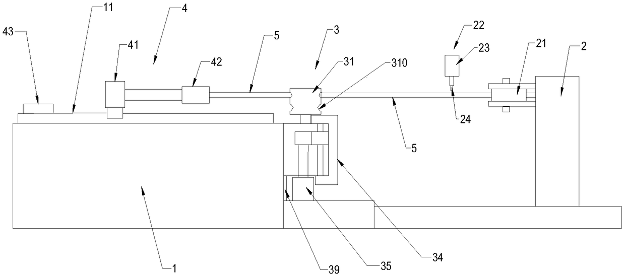
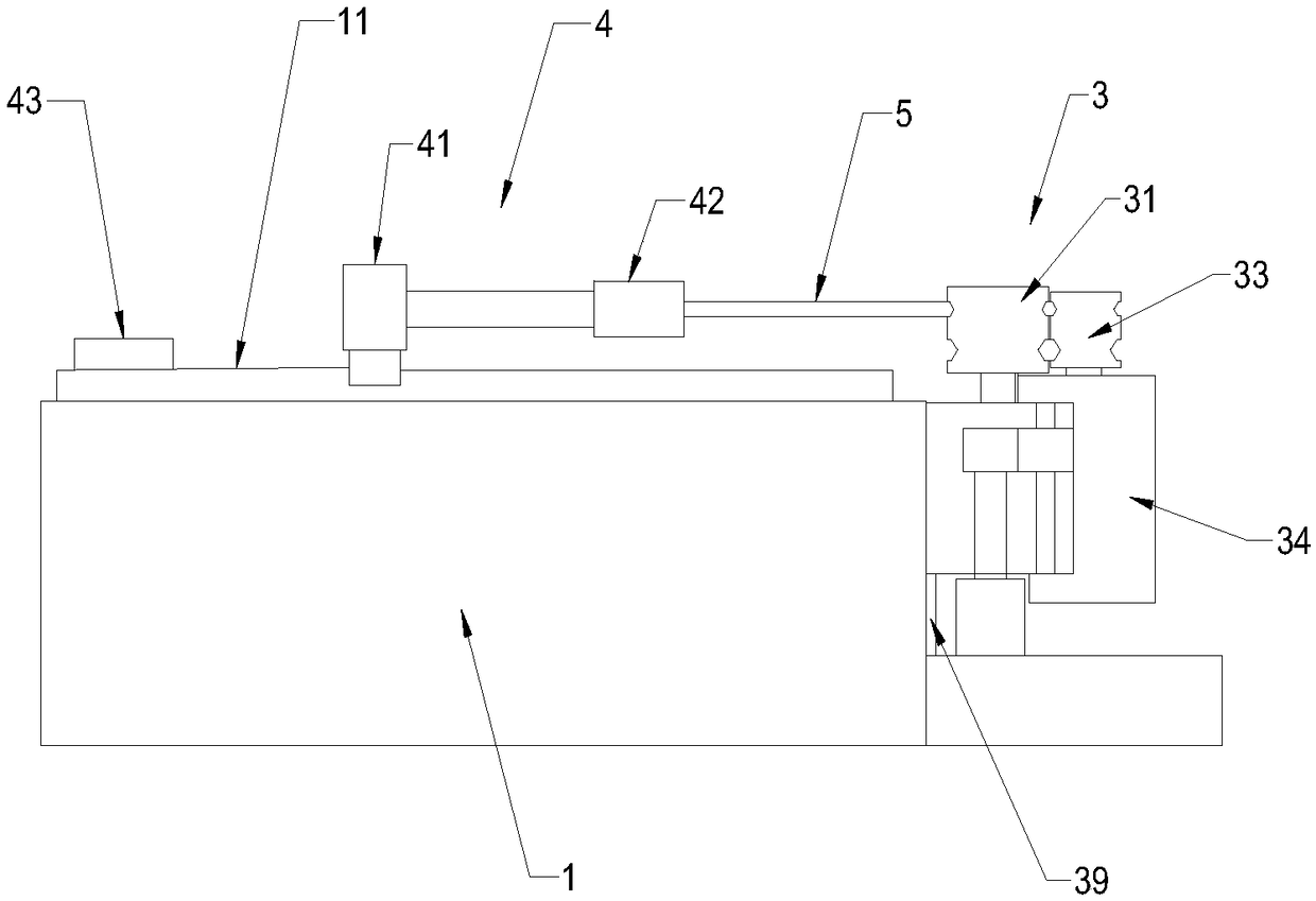
[0020] Such as figure 1 As shown in -3, this embodiment provides a pipe bending machine, including a workbench 1 and a feeder 2, the feeder 2 is arranged outside one end of the workbench 1, and the upper end surface of the workbench 1 is provided with a first slide rail 11, The clamping device 4 is arranged on the first slide rail 11, and the clamping device 4 is arranged on the first slide rail 11 through the cooperation of the slide block and the first slide rail 11. The workbench 1 is provided with a clamping motor 43 and a clamp Hold the screw, the bottom of the clamping device 4 is threadedly connected to the clamping screw, the clamping scr...


PUM


Abstract

The invention discloses a pipe bending machine which comprises a workbench (1) and a feeder (2). The feeder (2) is arranged on the outer side of one end of the workbench (1), and a first sliding rail(11) is arranged on the upper end face of the workbench (1). A clamping device (4) is slidingly arranged on the first sliding rail (11), and the bottom of the clamping device (4) can slide back and forth in the extending direction of the first sliding rail (11) through cooperation of the clamping lead screw and a clamping motor (43). The clamping device (4) comprises a pipe motor (41), and a clamping pipe (42) arranged at the end of an output shaft of the pipe motor (41). The clamping pipe (42) is in a polygon shape consistent with the shape of a pipe (5) to be bent. A bending device (3) is arranged between the clamping pipe (42) and the feeder (2). According to the pipe bending machine, the polygonal pipe can be continuously bent in multiple planes, and bending efficiency is improved.

Description

technical field [0001] The present invention relates to pipe benders. Background technique [0002] The pipe bending machine is used to bend the pipe fittings. At present, the mechanical pipe bending industry often uses the methods of pushing pipes, pulling bends, winding bends, pressing bends, etc. to process bends. The current pipe bender can only bend a straight The pipe fittings are bent in the horizontal plane. If the pipe fittings to be formed need to be bent in multiple planes, multiple pipe bending machines are required for bending or the pipe fittings in the first horizontal plane are bent, and then the pipe fittings are bent. Making another horizontal bend is inefficient. Contents of the invention [0003] In order to overcome the above disadvantages, the object of the present invention is to provide a pipe bender capable of continuously bending polygonal pipes on multiple planes and improving the bending efficiency. [0004] In order to achieve the above purpo...

Claims


Application Information

Patent Timeline
IPC IPC(8): B21D7/08B21D43/00B21D43/08B21D43/28
CPCB21D7/08B21D43/003B21D43/006B21D43/08B21D43/285
Inventor 阳江斌
Owner 张家港市越泰精密机械有限公司
Why Eureka
Try Eureka