Rubber roller placing frame of printer

A technology of rubber rollers and racks, applied to external frames, packaging, external accessories, etc., can solve problems such as inconvenient movement, unreasonable force, and poor adaptability, and achieve convenient adjustment, strong adaptability, and scientific force Effect

Pending Publication Date: 2018-11-13
芜湖市华美工艺包装有限公司
View PDF8 Cites 2 Cited by
  • Summary
  • Abstract
  • Description
  • Claims
  • Application Information

AI Technical Summary

Problems solved by technology

[0004] The purpose of the present invention is to overcome the deficiencies of the prior art, to provide a placement rack with a reasonable structural design, which can conveniently and quickly place the rubber rollers of the printing machine, so as to solve the movement of the rubber roller placement rack in the prior art. Technical problems such as inconvenience, poor adaptability and unreasonable force

Method used


Image

  • Rubber roller placing frame of printer
  • Rubber roller placing frame of printer
  • Rubber roller placing frame of printer

Examples


Embodiment 1

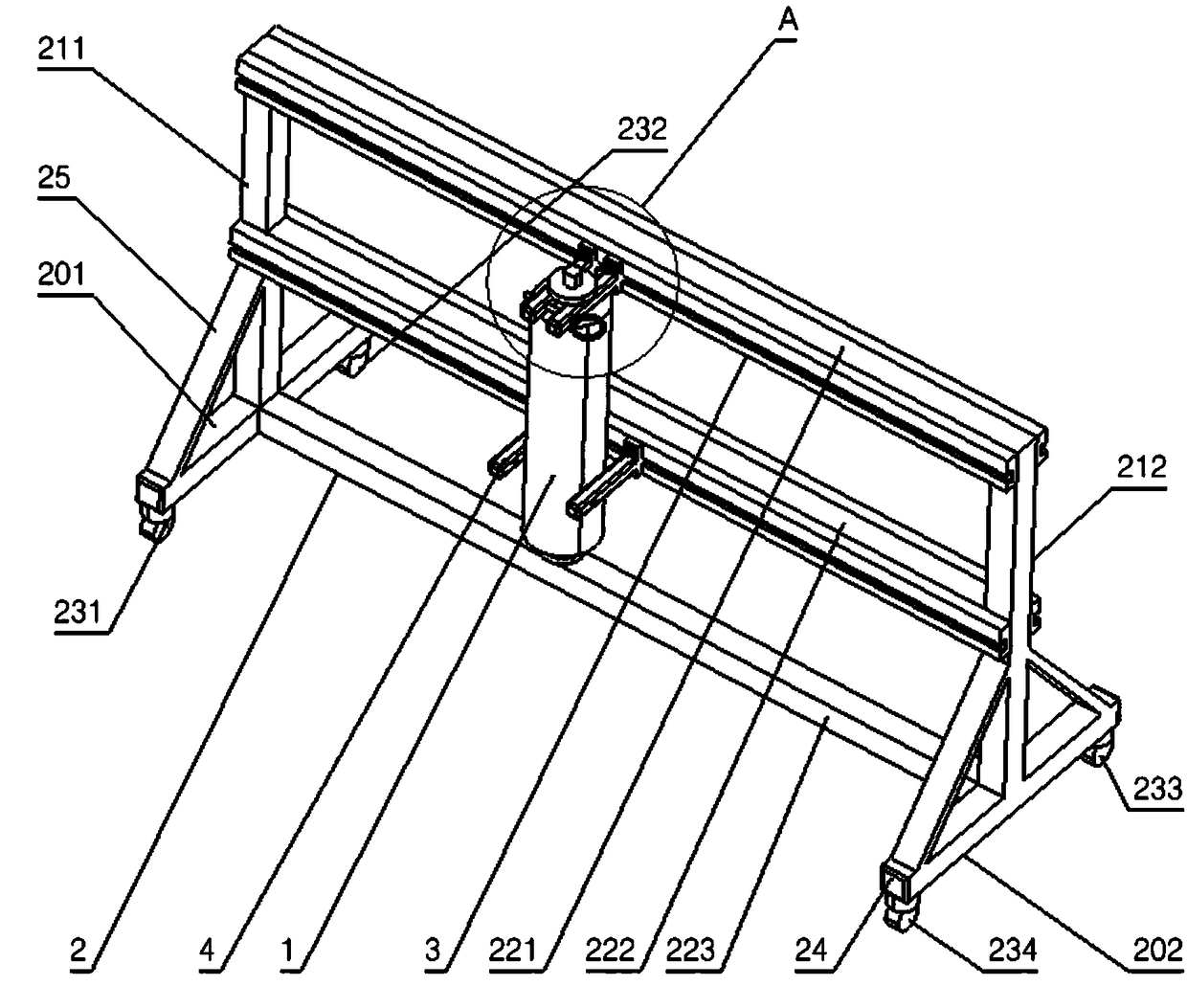
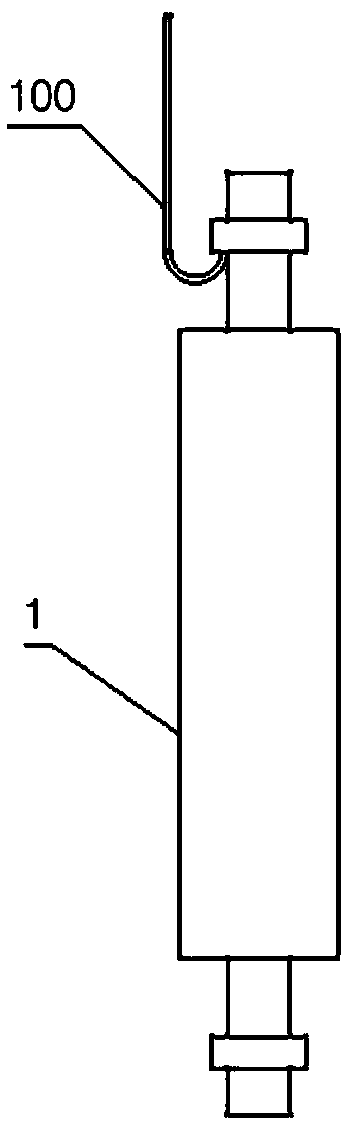
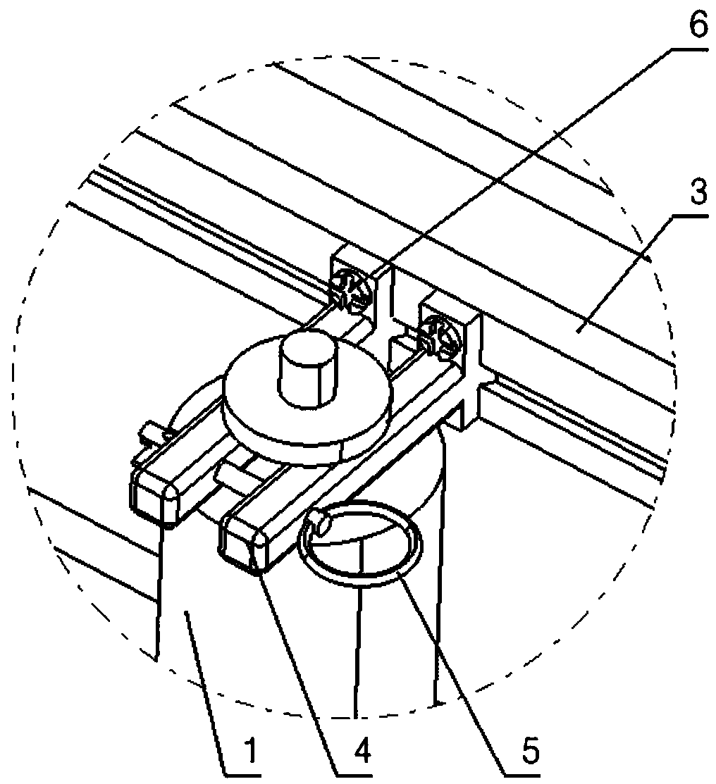
[0019] Embodiment 1 discloses a rubber roller placement frame for a printing machine and shows a situation where a rubber roller is fixedly placed, such as figure 1 with image 3 shown. The printing machine rubber roller placement frame includes a main body support 2 , a slide rail 3 , a sliding support arm 4 , a safety pin 5 and a set screw 6 . Wherein, the main frame 2 is composed of two bottom longitudinal beams 201 and 202 arranged in parallel, two uprights 211 and uprights 212 respectively connected to the midpoint of the upper surface of the bottom longitudinal beams, and one top beam connected between the tops of the uprights. 221 and a middle beam 222 connected between the middle of the columns and a ground beam 223 connected between the midpoints of the bottom longitudinal beams are welded. Bottom longitudinal beam 201 and bottom longitudinal beam 202 bottom two ends are installed caster 231, caster 232, caster 233 and caster 234 by screw. The slide rail 3 is fixe...

Embodiment 2

[0022] Embodiment 2 discloses a rack for placing a rubber roller of a printing machine and shows a situation in which a rubber roller is fixedly placed. The printing machine rubber roller placement frame includes a main body support 2 , a slide rail 3 , a sliding support arm 4 , a safety pin 5 and a set screw 6 . Wherein, the main body support consists of two bottom longitudinal beams 201 and 202 arranged in parallel, two uprights 211 and uprights 212 respectively connected to the midpoint of the upper surface of the bottom side beams, and one top beam 221 connected between the tops of the uprights. It is welded with a middle beam 222 connected between the middle parts of the uprights and a ground beam 223 connected between the middle points of the bottom longitudinal beams. Bottom longitudinal beam 201 and bottom longitudinal beam 202 bottom two ends are installed caster 231, caster 232, caster 233 and caster 234 by screw. The slide rail 3 is fixedly installed on the sides o...


PUM


Abstract

The invention discloses a rubber roller placing frame of a printer. The rubber roller placing frame comprises a main body bracket, slide rails, slide supporting arms, safety pins and set screws, wherein the main body bracket consists of two bottom longitudinal beams, two stand columns, a top beam, a middle beam and a ground beam; the two ends of the bottom surface of each bottom longitudinal beamare each equipped with one foot wheel through a bolt; the slide rails are fixedly mounted on the front side surface and the rear side surface of the top beam and the middle beam through bolts; the slide supporting arms are inserted into the slide rails from dovetail-shaped tenons thereof; the safety pins are inserted into slide supporting arm transverse through holes in the top beam slide rails; and set screws are screwed into longitudinal screw holes of the slide supporting arms. The rubber roller placing frame aims to solve the technical problems such as inconvenient movement, poor adaptation and unreasonable stress in the prior art, and provides the placing frame which is perpendicular to a placing structure, can conveniently and quickly place the rubber roller, and does not affect theshape of the rubber roller.

Description

technical field [0001] The invention relates to the technical field of printing, in particular to a printing machine rubber roller placement frame. Background technique [0002] The printing machine rubber roller is a roller-shaped product made of metal or other materials as the core and the outer rubber is vulcanized. The rubber roller of the printing machine is generally composed of an outer rubber layer, an outer hard rubber layer, a metal core, a roll neck and a vent hole. At present, the rubber roller of printing machine is a core component of printing machinery, and its surface finish and geometric accuracy will have an important impact on the printing quality of printed matter. Especially when printing exquisite prints, small errors will reduce the overall effect of the prints, making the two sides of the folio printed products blurred or distorted. [0003] After the rubber roller of the printing machine is processed, it usually needs to be placed on a rack for air...

Claims


Application Information

Patent Timeline
Patent Type & Authority Applications(China)
IPC IPC(8): B65D61/00B65D25/24B65D85/20
CPCB65D25/24B65D61/00B65D85/20
Inventor 徐洁
Owner 芜湖市华美工艺包装有限公司
Why Eureka
Try Eureka