VR (virtual reality) device

A technology of equipment and lens barrel, which is applied in the field of optics and can solve problems such as fragile display screens

Active Publication Date: 2018-11-13
GOERTEK OPTICAL TECH CO LTD
View PDF7 Cites 3 Cited by
  • Summary
  • Abstract
  • Description
  • Claims
  • Application Information

AI Technical Summary

Problems solved by technology

If too much light reaches near the display, it can easily damage the display

Method used


Image

  • VR (virtual reality) device
  • VR (virtual reality) device
  • VR (virtual reality) device

Examples


Embodiment Construction

[0028] In order to make the purpose, technical solutions and advantages of the embodiments of the present invention clearer, the technical solutions in the embodiments of the present invention will be clearly and completely described below in conjunction with the drawings in the embodiments of the present invention. Obviously, the described embodiments It is a part of embodiments of the present invention, but not all embodiments. Based on the embodiments of the present invention, all other embodiments obtained by persons of ordinary skill in the art without creative efforts fall within the protection scope of the present invention.

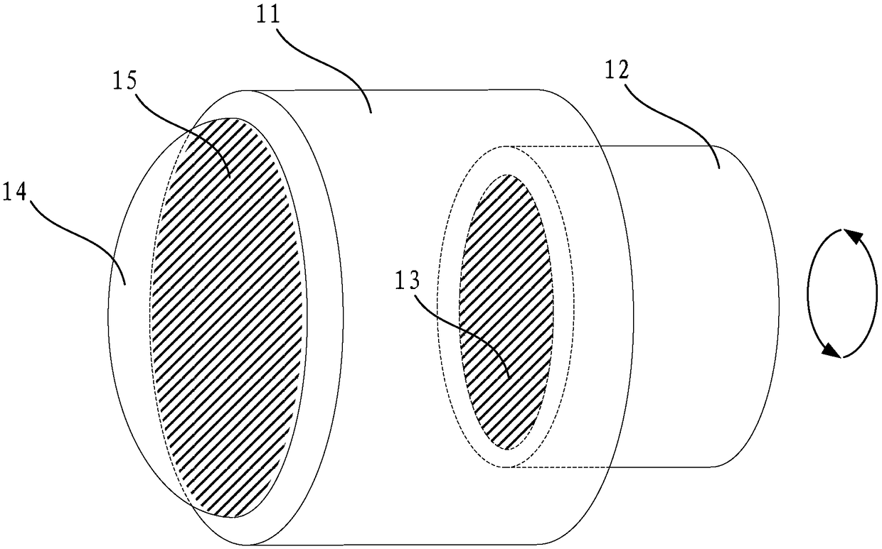
[0029] figure 1 is a schematic structural diagram of a VR device provided by an embodiment of the present invention, such as figure 1 As shown, the lens includes:

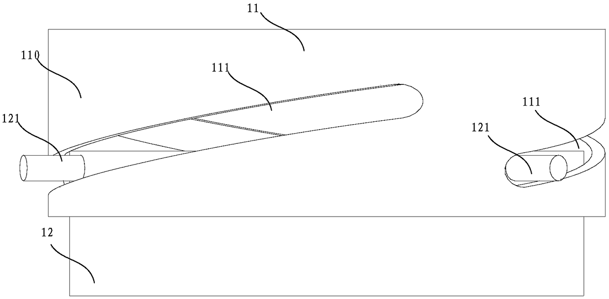
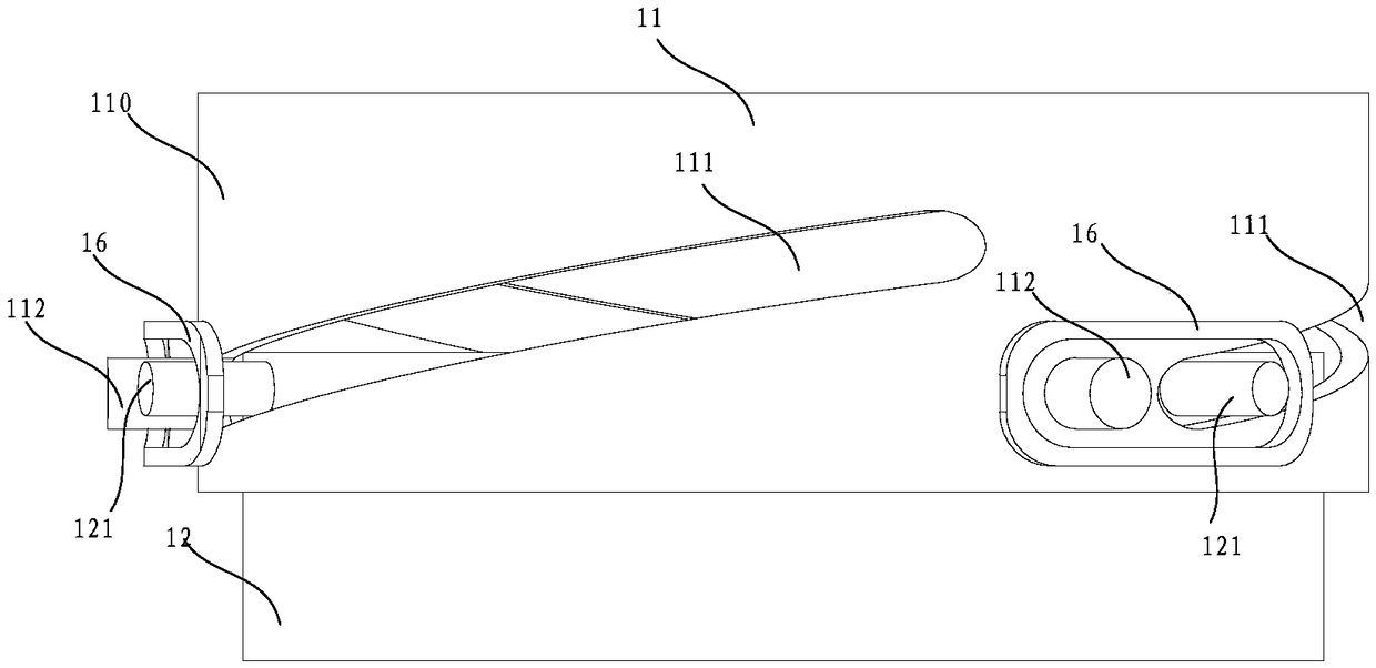
[0030] Relatively rotatable outer lens barrel 11, inner lens barrel 12, and lens 14 mounted on the inner lens barrel 12 and / or the outer lens barrel 11; one of the inner lens barrel ...


PUM


Abstract

The invention provides a VR (virtual reality) device. The device comprises an outer lens cone, an inner lens cone and a lens mounted on the inner lens cone and / or the outer lens cone, wherein the outer lens cone and the inner lens cone can rotate oppositely; a first polarizing film is mounted on one of the inner lens cone and the outer lens cone, and a second polarizing film is mounted on the other; when the inner lens cone and the outer lens cone rotate oppositely, polarization directions of the first polarizing film and the second polarizing film remain the same or different. The lens on theVR device can be shielded from light with the technical scheme.

Description

technical field [0001] The present invention relates to the field of optical technology, in particular to a VR device. Background technique [0002] VR (Virtual Reality, Virtual Reality) technology is a computer simulation system that can create and experience a virtual world. It uses a computer to generate a simulated environment, and through multi-source information fusion, interactive three-dimensional dynamic vision and entity behavior The system simulation immerses the user in this simulated environment. [0003] Existing VR devices include a lens for viewing virtual images, through which a user views a display screen fixed inside the VR device or detachably installed on the VR device. When the VR device is in an external environment with strong light, more light passes through the lens and reaches the vicinity of the display screen. If too much light reaches the vicinity of the display, it can easily damage the display. In order to solve this defect, a new VR device...

Claims


Application Information

Patent Timeline
IPC IPC(8): G02B27/01G02B27/28
CPCG02B27/0172G02B27/0176G02B27/281
Inventor 翟睿智姜滨
Owner GOERTEK OPTICAL TECH CO LTD
Why Eureka
Try Eureka