Gluing gun positioning mechanism of gluing robot

A technology of positioning mechanism and robot, which is applied to the device and coating of the surface coating liquid, which can solve the problems of displacement, defect and gun shaft shaking of the glue coating area

Active Publication Date: 2018-11-16
ANHUI RUIXIANG IND
View PDF8 Cites 3 Cited by
  • Summary
  • Abstract
  • Description
  • Claims
  • Application Information

AI Technical Summary

Problems solved by technology

[0002] At present, in the welding process of the automobile side wall, it is necessary to apply glue to the inner and outer panels of the side wall. The glue gun in the prior art is used to apply glue. When the place where the inner and outer panels need to be glued is a curve, the shaking range becomes larger and deviates from the predetermined glued position, and the rubber strip will bend or the glued area will shift, resulting in the rubber strip becoming invalid or the glued seal being poor.

Method used


Image

  • Gluing gun positioning mechanism of gluing robot
  • Gluing gun positioning mechanism of gluing robot
  • Gluing gun positioning mechanism of gluing robot

Examples


Embodiment Construction

[0028] In the present invention, it should be understood that the terms "length", "width", "upper", "lower", "front", "rear", "left", "right", "vertical", "horizontal" ", "Top", "Bottom", "Inner", "Outer", "Clockwise", "Counterclockwise", "Axial", "Radial", "Circumferential" and other indications are based on The orientation or positional relationship shown in the drawings is only for the convenience of describing the present invention and simplifying the description, and does not indicate or imply that the referred device or element must have a specific orientation, be constructed and operated in a specific orientation, and therefore cannot be understood as Limitations on the Invention.

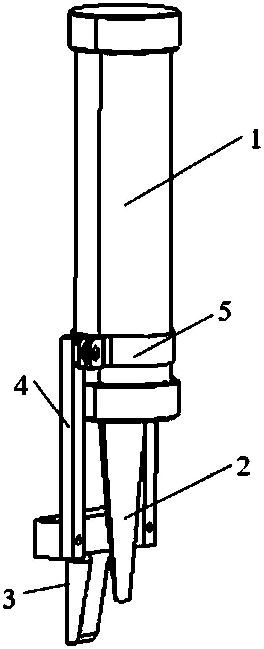
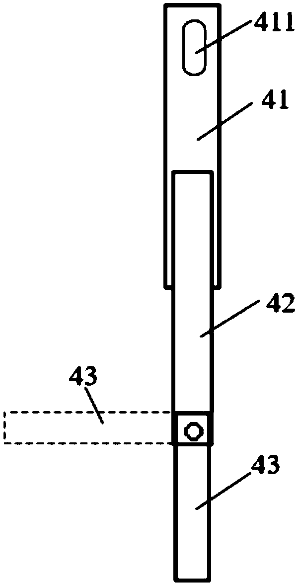
[0029] Such as Figure 1 to Figure 6 As shown, a gluing gun positioning mechanism of a gluing robot includes a gun bar 1, a gun nozzle 2, a guide mechanism 3 and a connecting bracket 4, and one end of the connecting bracket 4 is connected to the gun bar 1 by a clip 5, and the connecting bra...


PUM


Abstract

The invention discloses a gluing gun positioning mechanism for a gluing robot. The gluing gun positioning mechanism comprises a gun rod, a gun nozzle, a guiding mechanism and a connecting support, oneend of the connecting support is connected to the gun rod through a clamp, and the other end of the connecting support is connected with the guiding mechanism. A gap is arranged between the guiding mechanism and the gun nozzle, and one the side, close to the nozzle, of the guiding mechanism is attached to a car body panel, so the movement of the gluing gun along the automobile body panel in the gluing process is ensured, that is the position of the gluing gun is fixed, and the gluing gun clamped on the automobile body panel slides with the automobile body panel. When the glue gun is used in dispensing or local small-range gluing, the gun nozzle of the gluing gun needs to be in close contact with a coated position, and the connecting support is designed to be a telescopic structure and comprise a connecting rod I and a connecting rod II in order to avoid interference between the guiding mechanism and other components, wherein the connecting rod II is nested in the connecting rod I, a kidney-shaped hole is arranged at one end of the connecting rod I, the connecting rod I goes through the kidney-shaped hole and is connected to the clamp through a fastener, and the guiding mechanism is connected to the connecting rod II.

Description

technical field [0001] The invention belongs to the technical field of gluing for automobile welding, and in particular relates to a gluing gun positioning mechanism of a gluing robot. Background technique [0002] At present, in the welding process of the automobile side wall, it is necessary to apply glue to the inner and outer panels of the side wall. The glue gun in the prior art is used to apply glue. When the place where the inner and outer panels need to be glued is a curve, the shaking range becomes larger, and the predetermined glueing position deviates, and the rubber strip bends or the glued area shifts, resulting in the rubber strip being invalid or the glued seal is not good. Contents of the invention [0003] In view of the deficiencies in the prior art, the purpose of the present invention is to provide a glue gun positioning mechanism of a glue-applying robot. When applying glue, the positioning mechanism leans against the automobile panel to realize the po...

Claims


Application Information

Patent Timeline
Patent Type & Authority Applications(China)
IPC IPC(8): B05C5/02B05C11/00B05C7/06
CPCB05C5/0204B05C7/06B05C11/00
Inventor 王伟罗伟庞先伟
Owner ANHUI RUIXIANG IND
Why Eureka
Try Eureka