
Simultaneous cutting system for pipe extrusion

A synchronous cutting and piping technology, applied in metal sawing equipment, metal processing equipment, manufacturing tools, etc., can solve problems such as burrs, debris, and loud noise

Active Publication Date: 2019-11-26
ZHEJIANG JINBO FLUID CONTROL
View PDF5 Cites 0 Cited by
  • Summary
  • Abstract
  • Description
  • Claims
  • Application Information

AI Technical Summary

Problems solved by technology

[0002] At present, the equipment used for pipe cutting in the production process is generally used for cutting with planetary saw blades. During the cutting process, debris will be generated, the section will be rough, there will be burrs, and the noise will be large.
Moreover, most of the existing cuttings are fixed cutting

Method used


Image

  • Simultaneous cutting system for pipe extrusion
  • Simultaneous cutting system for pipe extrusion
  • Simultaneous cutting system for pipe extrusion

Examples


Embodiment Construction

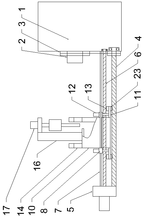
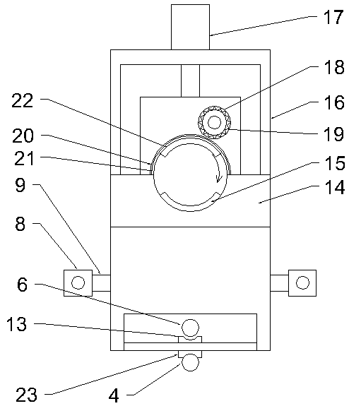
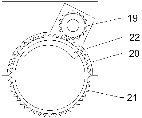
[0017] Below in conjunction with all accompanying drawings the present invention will be further described, and preferred embodiment of the present invention is: see appended figure 1 to attach Figure 5 The synchronous cutting system for pipeline extrusion described in this embodiment includes an extruder 1, a synchronous gear 3 is installed on the rotating head 2 of the extruder 1, and the bottom of the extruder 1 below the synchronous gear 3 is extruded along the A lower transmission screw 4 is installed in the output direction, one end of the lower transmission screw 4 is installed at the bottom of the extruder 1, and the other end is installed in the outer limit seat 5, and the lower transmission screw 4 and the synchronous gear 3 are connected by a chain; the lower transmission screw 4 An upper transmission screw 6 is installed between the upper extruder 1 and the outer limit seat 5, and the upper drive screw 6 is driven to rotate by the rotating motor inside the outer l...


PUM


Abstract

The invention provides a synchronous cutting system for pipeline extrusion. The synchronous cutting system comprises an extruder; a synchronous gear is mounted on a rotating extruder head of the extruder; a lower transmission screw rod is mounted below the synchronous gear; an upper transmission screw rod is mounted on the position, above the lower transmission screw rod, between the extruder andan outer limiting seat; guiding sliding shafts are arranged on the two sides of the upper portion of the upper transmission screw rod; one ends of the guiding sliding shafts are fixed into the outer limiting seat, and the other ends of the guiding sliding shafts are fixed into the extruder; each guiding sliding shaft is movably sleeved with two sliding sleeves; the two sliding sleeves on the samepositions of the two guiding sliding shafts are connected through a connecting plate; a cutting frame is movably mounted between the two connecting plates; pipeline positioning supporting plates are arranged on the two sides of the top of the cutting frame; and a cutting assembly is mounted on the position, between the two pipeline positioning supporting plates, of the cutting frame. After the synchronous cutting system is adopted, the structure is reasonable, meanwhile, cutting noise is low, burrs are basically avoided, and the using effect is excellent.

Description

technical field [0001] The invention relates to the technical field of pipe production, in particular to a synchronous cutting system for pipe extrusion. Background technique [0002] At present, the equipment used for pipe cutting in the production process is generally used for cutting with planetary saw blades. During the cutting process, debris will be generated, the section will be rough, there will be burrs, and the noise will be large. And most of the existing cuttings are fixed cuttings. Contents of the invention [0003] The object of the present invention is to overcome the disadvantages of the prior art and provide a synchronous cutting system for pipe extrusion with reasonable structure, low cutting noise, basically no burrs and excellent use effect. [0004] In order to achieve the above purpose, the technical solution provided by the present invention is: a synchronous cutting system for pipe extrusion, which includes an extruder, a synchronous gear is instal...

Claims


Application Information

Patent Timeline
Patent Type & Authority Patents(China)
IPC IPC(8): B23D57/00
CPCB23D57/00
Inventor 贺春香
Owner ZHEJIANG JINBO FLUID CONTROL
Learn More