Advanced automatic charging pile

A technology of automatic charging and charging piles, which is applied in electric traction, electric vehicles, transportation and packaging, etc. It can solve the problems of affecting the service life of charging piles, easy to generate arcs, and exposed electrical ports, so as to achieve convenient automatic plugging and charging, Increased safety performance and convenient connection

Inactive Publication Date: 2018-11-16
广州吉和电子商务有限公司
View PDF1 Cites 0 Cited by
  • Summary
  • Abstract
  • Description
  • Claims
  • Application Information

AI Technical Summary

Problems solved by technology

[0002] At present, the country is vigorously promoting the development of new energy vehicles. New energy vehicles are inseparable from charging piles. During the process, an arc is likely to be generated due to the influence of the voltage. The generation of the arc is likely to cause electric shock to the user. It has a certain potential danger to the user, which will caus

Method used


Image

  • Advanced automatic charging pile
  • Advanced automatic charging pile
  • Advanced automatic charging pile

Examples


Embodiment Construction

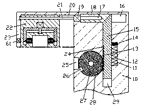
[0014] Combine below Figure 1-3 The present invention will be described in detail.

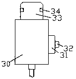
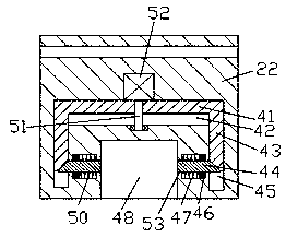
[0015] refer to Figure 1-3 , an advanced automatic charging pile according to an embodiment of the present invention, includes a charging pile body 10 and a charging gun 30 installed on the charging pile body 10, and a protrusion is fixed on the top of the left end surface of the charging pile body 10 part 23, the bottom end surface of the convex part 23 is provided with a first chute 20, the first slider 22 is slidably fitted in the first chute 20, and the bottom end surface of the first slider 22 is provided with a first A slot 48, the inner walls of the left and right sides of the first slot 48 are symmetrically provided with locking mechanisms, the first slider 22 is threadedly fitted with a first screw 21, and the left extension end of the first screw 21 is connected to the The inner wall on the left side of the first chute 20 is rotatably connected, and the extension end on the right...


PUM


Abstract

The invention discloses an advanced automatic charging pile comprising a charging pile body and a charging gun mounted on the charging pile body. A convex part is fixedly arranged at the top end of the left side end face of the charging pile body. A first sliding groove is formed in the bottom end face of the convex part. A first sliding block is mounted in the first sliding groove in a sliding fit mode. A first inserting groove is formed in the bottom end face of the first sliding block. Locking mechanisms are symmetrically arranged in the inner walls of the left side and the right side of the first inserting groove. A first threaded rod is mounted on the first sliding block in a threaded fit mode. The extending tail end of the left side of the first threaded rod is connected with the inner wall of the left side of the first sliding groove in a rotating fit mode. The extending tail end of the right side of the first threaded rod is in power connection with a first motor. The outer surface of the first motor is fixedly arranged in the left side end face of the charging pile body. A second inserting groove is formed in the position, on the lower side of the convex part, of the leftside end face of the charging pile body. A rotating cavity is formed in the inner wall of the right side of the second inserting groove in a communicating mode.

Description

technical field [0001] The invention relates to the technical field of new energy, in particular to an advanced automatic charging pile. Background technique [0002] At present, the country is vigorously promoting the development of new energy vehicles. New energy vehicles are inseparable from charging piles. During the process, an arc is likely to be generated due to the influence of the voltage. The generation of the arc is likely to cause electric shock to the user. It has a certain potential danger to the user, which will cause a safety accident and cause casualties. Moreover, the force of the personnel on the plug is unstable, which may easily lead to equipment damage. Moreover, the power connection port of the traditional charging pile is usually not sealed and protected, and the exposed power connection port is easy to enter dust, etc., which affects the service life of the charging pile. Contents of the invention [0003] The object of the present invention is to...

Claims


Application Information

Patent Timeline
IPC IPC(8): B60L11/18
Inventor 余小兰
Owner 广州吉和电子商务有限公司
Why Eureka
Try Eureka